Register
address
Marking
Opera-
tion
Parameter
range
Description
4000 -W 1…6
Register of commands:
1 – input in the automatic control
mode
2 – input in the manual control mode
3 – beginning of the auto-tuning
4 – erasing of alarm memory
5 – restoration of manufacturer’s
settings (apart interface settings and
defi ned programs)
6 – restoration of manufacturer’s
settings of defi ned programs.
4001 R- 100…999 Number of program version [x100]
4002 R-
Version code of the controller:
bit 2 1 0 – OUTPUT 1:
0 0 1 – output 1 – relay
0 1 0 – output 1 – 0/5 V
0 1 1 – output 1 – continuous
current : 0/4…20 mA
1 0 0 – output 1 – continuous
voltage: 0…10 V
bit 5 4 3 – OUTPUT 2:
0 0 1 – output 2 – relay
0 1 0 – output 2 – 0/5 V
0 1 1 – output 2 – continuous
current: 0/4…20 mA
1 0 0 – output 2 – continuous
voltage: 0…10 V
bit 8 7 6 – OPTIONS:
0 0 1 – output 3 - relay
0 1 0 – binary input
0 1 1 – current transformer input
1 0 0 – additional current input:
0/4…20 mA
1 0 1 – supply of transducers:
24V d.c. 30 mA
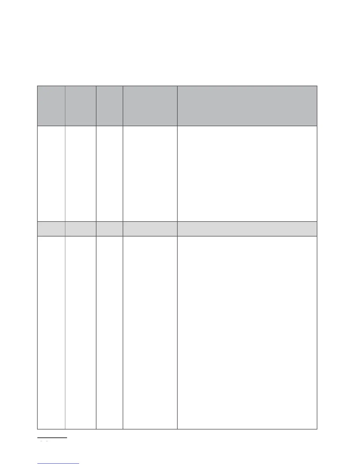
In the controller, data are situated in 16-bit registers. The list
of registers for write and readout
is presented in the table 11.
Operation „R-” – means the possibility of readout, and the operation
„RW” means the possibility for readout and write.
Map of registers from address 4000
Table 11
 Loading...
