A-12
A.6 Instructions for correct EMC installation
According to EMC, means:
The VF1000M inverter series has been so developed, that not only the
Low Voltage Directive is complied with, but also with suitable measures,
the EMC Directives - even strict directives for residential areas can be
observed. The acceptance of the device takes place under laboratory
conditions at the accredited Schenk Commercial Test Centre and is not
bindingly transferrable to a machine or system in its installed condition.
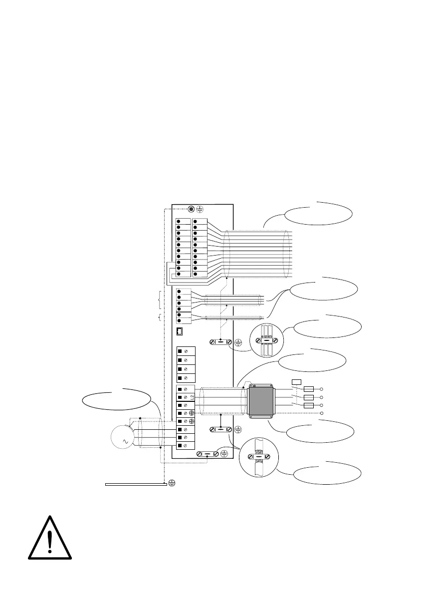
Installation information is given in the diagram below to aid the achievement
of optimum installation.
You will achieve correct EMC installation ...
1
Necessary cable lengths > 0.3 m
Important: For further information see Chapter 2
-
RB RB +
41
42
43
44
45
46
n.c.
23
29
36
21
22
23
24
25
26
33
34
35
26
47
48
49
50
51
52
RS232/RS485
W V U L3 L1
M
3
K1
SI
L1
L2
L3
PE
3 x 400/460VAC
SI
SI
PTC
X6/1
X6/2
X5
X4
X3
X2
X1
... with screened
motor cable
... with screened
control cable
> 10 mm
2
Stem point (main
ground) in cabinet
... with screened
control cable
... with screened
control cable
... with screened
motor cable
(1
... with mains filter
see Chap. 2.2
... with screened
control cable
,
,,,
,,,,
,,,
,,
L2
 Loading...