2-11
2.4.3 Control functions with STR/STL
Mains connection with STL/STR
For reasons of safety, the inverter may not be connected to the mains
with the preselected control function STL or STR. The start function
does not recognize the inverter until it has been activated after power on
and self-test.
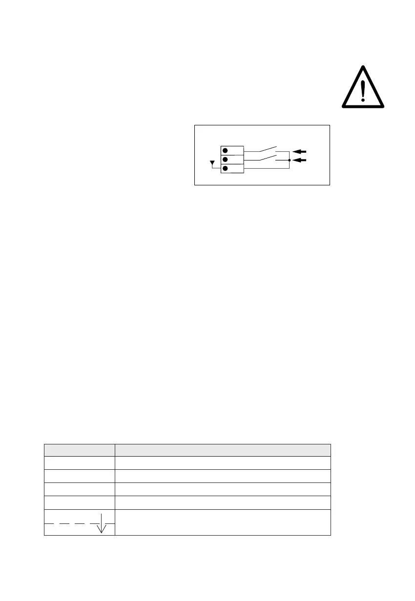
The direction of rotation is selected
via the inputs STR or STL, using 2
switch contacts according to the
circuit diagram. Alternatively,
direction of rotation selection via 2
external voltage signals according
to the specification of the control
connections is also possible.
24
25
26
+24V
STR
STL
X6/2
START
The inverter starts up when an STL or STR control signal and a reference
for the rotary field frequency of at least 0.5 Hz = 0.1 V at FSIN are available.
STOP
The inverter stops when the STL or STR control signals are returned. The
connected motor comes to a halt by itself, i.e. without braking.
BRAKING/STOP
The inverter brakes the motor until STOP, when two control signals are
simultaneously available at STL and STR. When both signals are set to
zero there is a restart.
REVERSING
The direction of rotation is reversed if the control signal is changed directly
from one control input (e.g. STL) to another (e.g. STR).
The overlap time must be a min. of 8 ms.
STL STR Explanation
0 0 STOP, Motor uncontrolled
1 0 START, Counter-clockwise with RACC/RDEC
0 1 START, Clockwise with RACC/RDEC
1 1 BRAKING, Motor is controlled to STOP
0 1 Reverse direction of rotation
10
 Loading...