1-1
1 Technical data
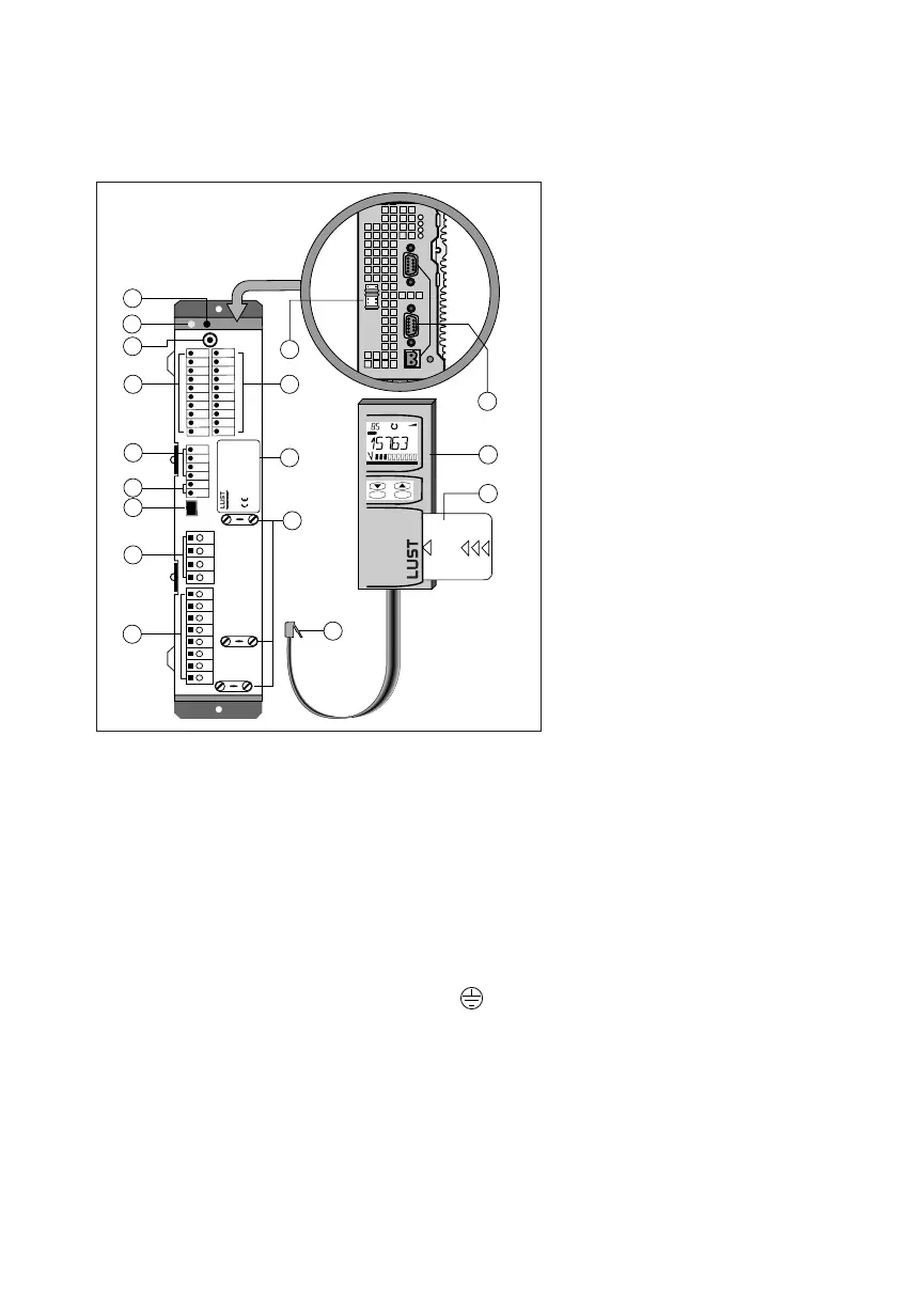
1.1 Assembly and layout plan
1 LED H2 (green) operation
indicator
2 LED H1 (yellow) error indicator
3 Terminal X6/1 control outputs
4 Terminal X6/2 control inputs
5 Terminal X5 for interface design
(RS485/RS232)**
6 Terminal X4, for motor PTC**
7 Connection socket for X3 for
control unit K
EYPAD KP100
8 Terminal X2, connection for ext.
braking resistance* and
DC-link coupling (+,-)
W V U PE PE L3
N/L2
L1
- RB RB +
41
42
43
44
45
46
n.c.
23
29
36
21
22
23
24
25
26
33
34
35
26
47
48
49
50
51
52
13
stop
return
start
enter
VAL
Hz
SMART
CARD
12
3
6
8
9
2
1
4
11
10
7
5
17
15
SN:----.V--.- --10000
Gerät:
Typ:
Netz:
Ausg:
16
+
14
* Accessories, see data booklet VF1000
** Designs, see data booklet VF1000
9 Terminal X1 power connections
10 K
EYPAD plug
11 EMC ground clamps for cable
screen
12 Control unit K
EYPAD KP100*
13 SMARTCARD* memory card
14 Jumper rail J1 ... J6
15 Connecting point for groun-
ding line
16 Type plate
17 Bus connections (CAN-Bus,
INTERBUS-S, ...)**
 Loading...