


G
Gary DavisSep 1, 2025
How to troubleshoot 'EOP High' error on Magnetrol Measuring Instruments?
- EEmily WoodSep 1, 2025
If the End of Probe signal is out of range, ensure the Probe Length is entered correctly.
How to troubleshoot 'EOP High' error on Magnetrol Measuring Instruments?
If the End of Probe signal is out of range, ensure the Probe Length is entered correctly.
What to do if LEVEL reading is correct but LOOP is stuck at 4 mA on Magnetrol Transmitter?
If the LEVEL reading on the Display is correct, but the LOOP is stuck on 4 mA, the basic configuration data might be questionable. Set the POLL ADR to 0 if you are not using HART multi-drop.
Why is the LEVEL value reading high when it should be zero on Magnetrol eclipse 705 Measuring Instruments?
If the LEVEL value is reading high when it should be zero, the transmitter might be loose or disconnected from the probe. Ensure the transmitter is securely connected to the probe.
Why is LEVEL reading high when it should be zero on Magnetrol Transmitter?
If the LEVEL value is reading high when it should be zero, the transmitter might be loose or disconnected from the probe. Ensure the transmitter is securely connected.
How to resolve WeakSgnl error on Magnetrol Transmitter?
If you are getting a WeakSgnl error, the signal amplitude is lower than desired. Set the transmitter to a lower dielectric range and increase the sensitivity.
What does 'FidShift' mean on Magnetrol Transmitter and how can I resolve it?
If you see 'FidShift', it means the FidTicks have shifted from the expected value. Check the connection between the probe and the transmitter, check for moisture on top of the probe, and check for a damaged gold pin on the high-frequency connector.
What does 'LVL < Probe Length' mean on Magnetrol Transmitter?
If 'LVL < Probe Length', the apparent position of the upper level pulse is beyond the end of the probe. Check the entered probe length and change the threshold to fixed.
What causes high LEVEL and % OUTPUT readings on Magnetrol eclipse 705?
If the LEVEL and % OUTPUT values are reading high compared to the actual level, there might be an obstruction in the tank affecting the single rod probe. Increase the Dielectric Range until the obstruction is ignored or relocate the probe away from the obstruction.
How to troubleshoot inaccurate LEVEL and % OUTPUT values on Magnetrol Measuring Instruments?
If the LEVEL and % OUTPUT values are inaccurate, the basic configuration data might be questionable, or the interface level may have significant emulsion. You can reconfigure the Probe Model, Probe Mount, Probe Length, or Level Offset. Also, examine the process to reduce or eliminate the emulsion layer.
What to do if the LEVEL reading is stuck at full scale on Magnetrol eclipse 705?
If the LEVEL reading on the display is stuck at full scale, the software might believe the probe is flooded. Check the actual level. If the probe isn't flooded, inspect for buildup or obstructions near the top of the probe. You may also select a higher dielectric range, check for condensation in the probe connection, or add Blocking Distance.
Prerequisites and initial steps for installation.
Procedures for mounting the transmitter and probe.
Steps for making electrical connections.
Basic setup and configuration of the transmitter.
Procedures for safely unpacking the instrument.
Safety guidelines for handling sensitive electronic components.
Preparatory checks and considerations before installation.
Details on probe and transmitter mounting procedures.
Specific steps for installing coaxial probes.
Specific steps for installing twin rod probes.
Specific steps for installing single rod probes.
Procedures for attaching the transmitter unit.
Electrical connection procedures.
Wiring instructions for general purpose installations.
Wiring requirements for intrinsically safe installations.
Wiring procedures for explosion-proof environments.
Setup and calibration procedures.
Details on using the transmitter's interface and controls.
Detailed configuration steps for the Model 705 menu.
Configuration steps for level-only measurement.
Configuration for level and volume measurement.
Configuration for interface level measurement.
Explanation of the Level Offset parameter.
Procedure for linearizing output for odd-shaped vessels.
Setup and communication via HART.
How to connect a HART communicator.
Overview of the HART communicator's display menu.
Details on integrating with Fieldbus systems.
Overview of FOUNDATION fieldbus system.
Configuration steps for Fieldbus devices.
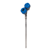
General overview of the ECLIPSE Level Transmitter.
Explanation of the technology and principles.
Explanation of the MIR technology.
How the device detects interface levels.
Diagnosing and resolving common problems.
Common system issues and their solutions.
Interpreting diagnostic messages and status indicators.
Certifications and compliance standards.
Information on replacement and spare parts.
List of components available for replacement.
Technical details and performance data.
Functional characteristics and parameters.
Performance metrics and accuracy details.
Physical dimensions and mounting information.
Product identification codes.
Breakdown of transmitter model number codes.
Breakdown of probe model number codes.
Details on warranty, repairs, and service.
Steps for returning materials for service or repair.
| Brand | Magnetrol |
|---|---|
| Model | eclipse 705 |
| Category | Measuring Instruments |
| Language | English |