16 06/02
DD
DD
D
CIAK 125 - 150CIAK 125 - 150
CIAK 125 - 150CIAK 125 - 150
CIAK 125 - 150
RIMOZIONE MOTORERIMOZIONE MOTORE
RIMOZIONE MOTORERIMOZIONE MOTORE
RIMOZIONE MOTORE
NotaNota
NotaNota
Nota: per rimuovere il motore è necessario rimuovere
preventivamente:
ABMONTIEREN DES MOTORSABMONTIEREN DES MOTORS
ABMONTIEREN DES MOTORSABMONTIEREN DES MOTORS
ABMONTIEREN DES MOTORS
HinweisHinweis
HinweisHinweis
Hinweis: Um den Motor auszubauen, erst folgende Teile
entfernen:
Posizionare lo scooter inPosizionare lo scooter in
Posizionare lo scooter inPosizionare lo scooter in
Posizionare lo scooter in
modo stabile ed iniziare glimodo stabile ed iniziare gli
modo stabile ed iniziare glimodo stabile ed iniziare gli
modo stabile ed iniziare gli
interventi di rimozione motore,interventi di rimozione motore,
interventi di rimozione motore,interventi di rimozione motore,
interventi di rimozione motore,
procedendo come segue:procedendo come segue:
procedendo come segue:procedendo come segue:
procedendo come segue:
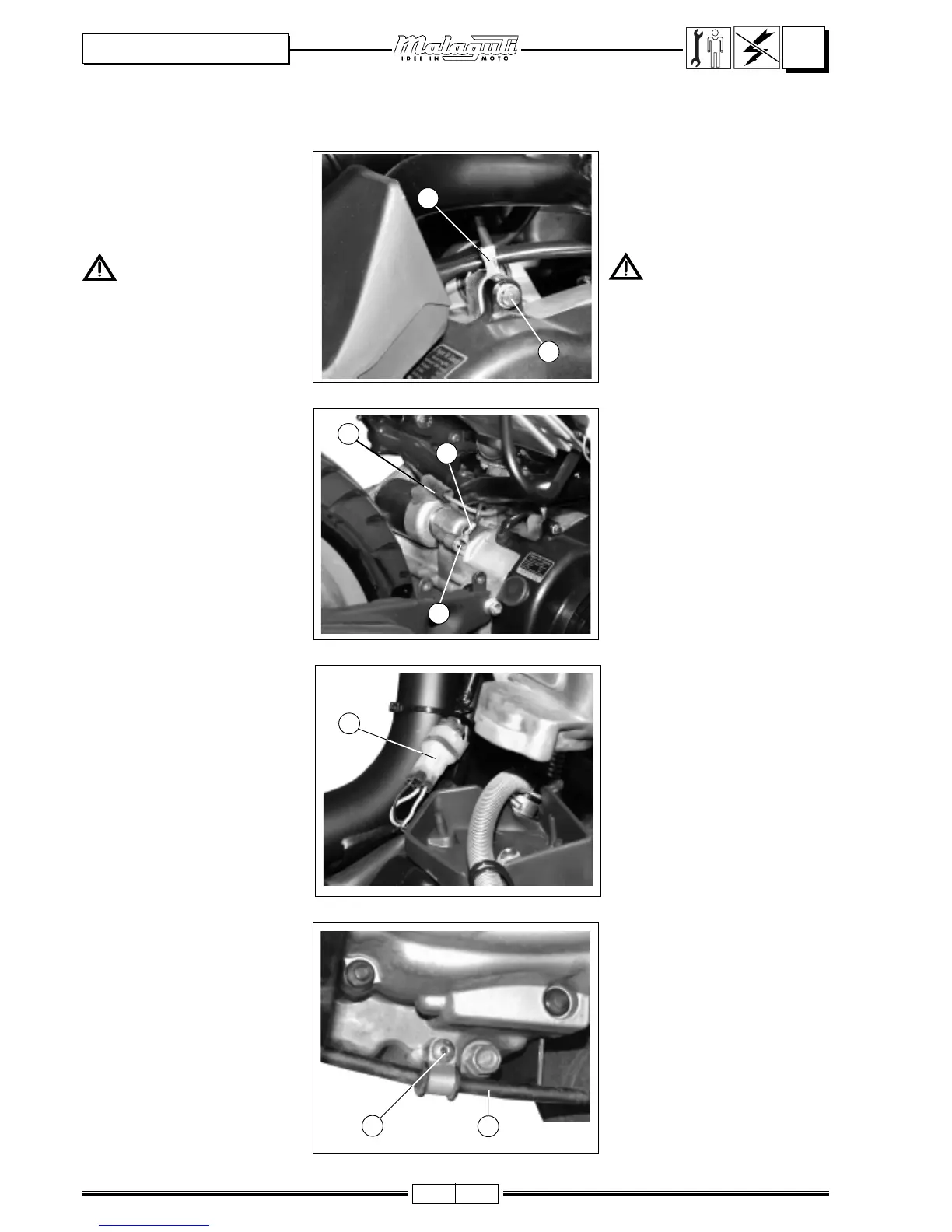
• Svitare la vite (V) e liberare il cavo
di massa (M).
• Svitare la vite (V1) e liberare il cavo
(M1) di massa motorino avviamen-
to.
•Scollegare il cavo (M2).
• Svitare la vite (1) e liberare il cavo
(2) per la trasmissione del freno
posteriore.
A) Vano casco (
S/C - P. 16S/C - P. 16
S/C - P. 16S/C - P. 16
S/C - P. 16 ).
B) Carenatura posteriore (
S/C - P. 18S/C - P. 18
S/C - P. 18S/C - P. 18
S/C - P. 18 ).
C) Scatola filtro aria (
S/S/
S/S/
S/
D D
D D
D
- P. - P.
- P. - P.
- P.
44
44
4).
D) Marmitta (
S/S/
S/S/
S/
D D
D D
D
- P. - P.
- P. - P.
- P.
88
88
8).
E) Ruota posteriore (
S/S/
S/S/
S/
D D
D D
D
- P. - P.
- P. - P.
- P.
1010
1010
10).
Das Kraftrad auf eineDas Kraftrad auf eine
Das Kraftrad auf eineDas Kraftrad auf eine
Das Kraftrad auf eine
stabile Oberfläche stellenstabile Oberfläche stellen
stabile Oberfläche stellenstabile Oberfläche stellen
stabile Oberfläche stellen
und die Arbeiten für den Ausbauund die Arbeiten für den Ausbau
und die Arbeiten für den Ausbauund die Arbeiten für den Ausbau
und die Arbeiten für den Ausbau
des Motors wie folgt vornehmen:des Motors wie folgt vornehmen:
des Motors wie folgt vornehmen:des Motors wie folgt vornehmen:
des Motors wie folgt vornehmen:
•Die Schraube (V) lockern und das
Massekabel (M) lösen.
A) Helmfach (
S/C - P. 16S/C - P. 16
S/C - P. 16S/C - P. 16
S/C - P. 16 ).
B) Hintere Verkleidung (
S/C - P. 18S/C - P. 18
S/C - P. 18S/C - P. 18
S/C - P. 18 ).
C) Luftfiltergehäuse (
S/D - P. 4S/D - P. 4
S/D - P. 4S/D - P. 4
S/D - P. 4).
D) Schalldämpfer (
S/D - P. 8S/D - P. 8
S/D - P. 8S/D - P. 8
S/D - P. 8).
E) Hinterreifen (
S/D - P. 10S/D - P. 10
S/D - P. 10S/D - P. 10
S/D - P. 10 ).
•Die Schraube (V1) lockern und
das Massekabel (M1) des
Anlassmotors lösen.
•Das Kabel (M2) trennen.
•Die Schraube (1) lockern und
das Kabel (2) zum Antrieb der
Hinterbremse lösen.
F. 21
F. 22
F. 24
MM
MM
M
VV
VV
V
VV
VV
V
11
11
1
22
22
2
11
11
1
MM
MM
M
11
11
1
F. 23
CC
CC
C
•Scollegare il connettore (C) del
volano magnete.
MM
MM
M
22
22
2
•Den Verbinder (C) des
Schwungrades trennen.
 Loading...