CRANKMECHANISM
Installingtheconnectingrodbearingcap
WARNING
Cracksurfacesaresensitive.The
principleinvolvedcancausechipping
•Exchangetheconnectingrodifthe
cracksurfacesaredamaged
•Protectcracksurfacesagainstdamage
causedbyhardandsharpobjects
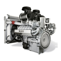
•Inserttheconnectingrodbearingshell(3)into
thecorrespondingconnectingrodbearingcap(2)
accordingtothemarkingandpairing;position
usingtheSettingtool[144]ifnecessary
•Fittheconnectingrodbearingcap(2)with
insertedconnectingrodbearingshell(3)onto
theconnectingrodasmarked,takingcare
nottodamagethecontactsurfacesbetween
theconnectingrodbearingshell(3)andthe
connectingrod
•Screwinthenewconnectingrodbearingbolts(1)
andtightenthembyhand
Tighteningtheconnectingrodbearingshells
•TurnthecrankshafttoBDCtotightenthe
connectingrodbearingbolts(1)
•Checkthealignmentoftheconnectingrod
bearings.Ifnecessary,removetheconnecting
rodbearingshellsandrepositiontheconnecting
rodbearingswithSettingtool[144],thenretthe
connectingrodbearings
•Tightentheconnectingrodbearingbolts(1)to
Initialtorque100Nm
•Tightentheconnectingrodbearingbolts(1)to
Finaltightening90°
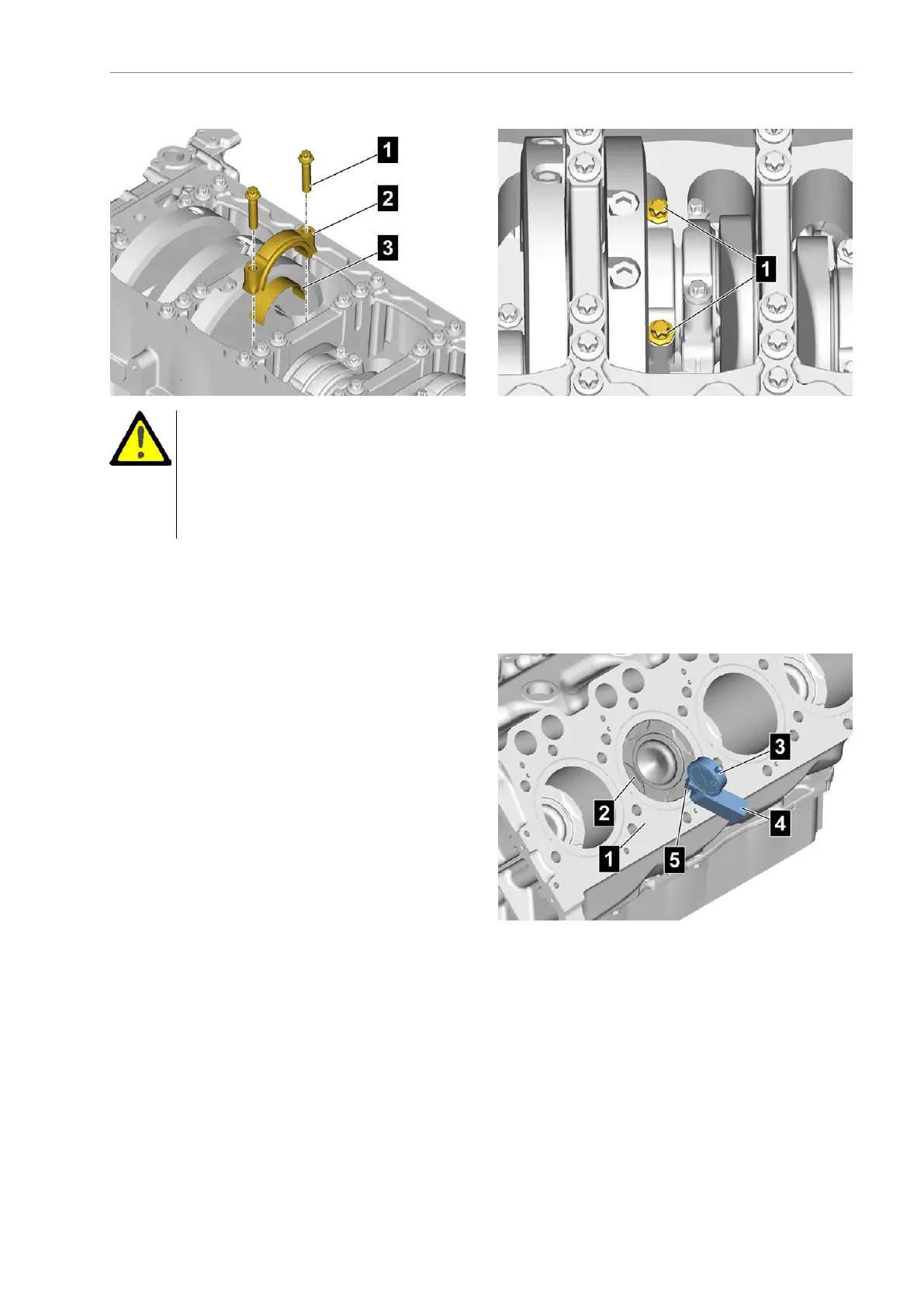
Measuringthepistonstandout
•Setthepiston(2)totopdeadcentre
•PuttheDialgauge[142](3)onthecrankcase(1)
withtheDialgaugeholder[140](4)
•Locatethedialgaugetip(5)onthecrankcase(1)
andzerotheDialgauge[142](3)
•Locatethedialgaugetip(5)onthepiston(2)and
readoffthedifference
Thepermittedpistonstandoutis-0.361to
+0.080mm.
AE63stedition331
 Loading...