SET-UP AND INSTALLATION 18000 OPERATOR MANUAL
4-12
Published 12-05-17, Control # 032-23
Deploy Rotating Bed Jacks
See Figure 4-9 for the following procedure.
NOTE If rotating bed is shipped with jacks installed, go
directly to step 2.
1. If jacks are not installed, proceed as follows:
a. Connect lifting slings from assist crane to lifting lugs
(5, View B) on jack (2).
b. Lift jack (2) into position so fixed pin (6, View B) in
jack engages hole in rotating bed and fixed pin (7) in
rotating bed engages hole in jack frame.
c. Lower jack into position and disconnect assist
crane.
d. Remove pin (8, View C) holding compression link
(9) in stored position.
e. Swing compression link into working position and
install pin (8, View C) in working position.
f. Remove strut (10, View D or F) and link (12a or 12b)
from stored position.
g. Install strut (10, View C or E) and link (12a or 12b) to
secure jack in working position.
h. Repeat step 1a through 1g for remaining jacks.
i. Go to step 3.
2. If rotating bed is shipped with jacks installed, proceed as
follows:
a. Remove pin (11a, View D or F) holding jack (2) in
stored position.
b. Rotate jack to working position.
c. Remove strut (10, View D or F) from stored position.
d. Install strut (10, View C or E) and link (12a or 12b) to
secure jack in working position.
e. Go to step 3.
Legend for Figure 4-9 and Figure 4-10
Item Description Item Description
1 Rotating Bed 8 Pin with Hair-Pin Cotters
2 Jack (4 each) 9 Compression Link
3 Operator’s Cab 10 Strut
4 Trailer 11 Pin — 1-1/8 in (28.6 mm) Dia x 4-3/4 in (60.3 mm) Long
5 Lifting Lug (2 each jack) 12a Link (rear)
6 Fixed Pin in Jack 12b Link (front)
7 Fixed Pin in Rotating Bed 13 Pin — 1-1/8 in (28.6 mm) Dia x 5 in (127 mm) Long
12b
12b
A
B
C
C
B
A
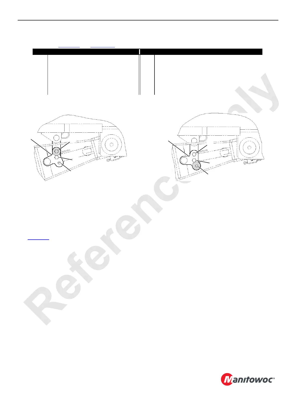
View A — Front Jacks Stored in
Crane Working Position
View B — Front Jacks Stored in
3,5 meter Shipping Position
NOTE Links (12b) must be assembled as shown for desired working
or shipping position. Note location of shaded lug and hole A.
FIGURE 4-10
 Loading...


