Manitowoc Published 12-05-17, Control # 032-23 4-55
18000 OPERATOR MANUAL SET-UP AND INSTALLATION
12. Continue to raise live mast while paying out boom hoist
wire rope.
Keep boom hoist rope as slack as possible to prevent
boom hoist wire rope from bearing against rope
guard in mast top (View G).
NOTE Operator shall match rate of speed at which mast
hoist wire rope is hauled in with rate of speed at
which boom hoist wire rope is payed out. Boom
hoist wire rope must remain slack until mast nears
vertical.
13. As mast nears vertical, tighten boom hoist wire rope as
required so mast moves smoothly past vertical to rear.
14. Continue to slowly haul in mast hoist wire rope and pay
out boom hoist wire rope to lower mast to rear.
15. As mast lowers, guide live mast straps into position at
rear of rotating bed (View L). Do not allow links to
contact hand rails on rear of crane.
16. Stop lowering mast when holes in live mast straps line
up with holes in rear of rotating bed. Connect straps to
rotating bed with pins and keeper plates provided (View
L).
NOTE Reference the live mast assembly drawing for
correct pin assembly configuration. Options include
standard pin configuration, MAX-ER configuration
with backhitch load pin, and shipping configuration
with MAX-ER backhitch load pin.
17. Pay out mast hoist wire rope until it starts to go slack.
Mast hoist wire rope must not go into tension during
crane operation.
18. Pay out boom hoist wire rope until mast stop guides
bottom out against mast stop pins (View J).
If necessary, adjust guides as follows (see View J):
a. Adjust slotted rod ends on mast stop struts so
engagement with pins takes place 1/3 to 1/2 of way
down rear side of saddle in both boom stop guides.
b. Adjust shims so boom stop guides bottom out
against pins within 1/8 in (3,2 mm) of each other.
19. If not already done, install boom and jib.
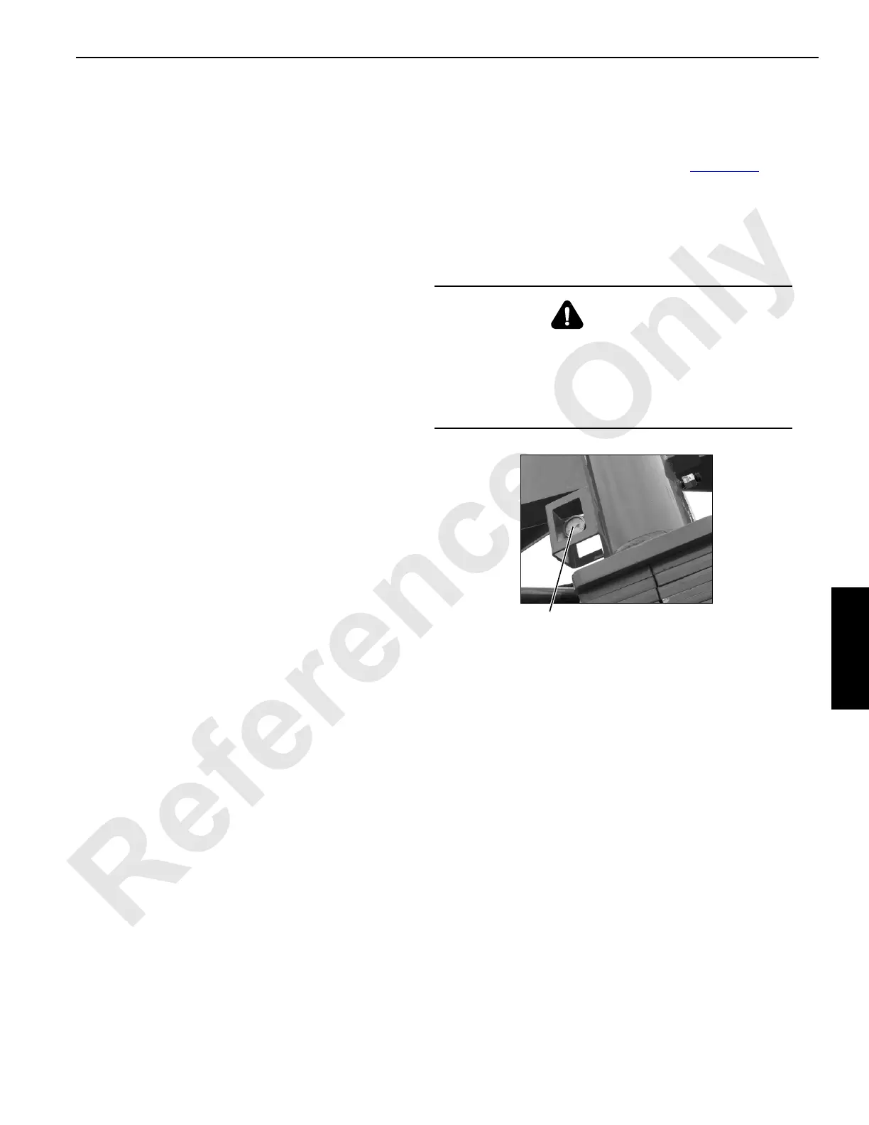
Check Mast Stop Pressure
If your crane is prepared for a MAX-ER attachment, each
mast stop has a hydraulic pressure gauge (Figure 4-31
).
Check both gauges WEEKLY. The gauges should read 200-
280 psi (13,8 - 19,3 bar) depending on outside air
temperature. If the proper reading is not indicated at either
gauge, determine cause of faulty pressure and take
corrective action.
Assemble and Install Boom and Jib
If not already done, assemble and install the desired boom
and jib combination. See Boom and Jib Rigging instructions
in this section and Boom and Jib Rigging drawings at the end
of this section.
If a luffing jib will be installed, see separate instructions in
Luffing Jib Operator Manual.
WARNING
Explosion Hazard!
Mast stop cylinders are equipped with nitrogen pre-
charged accumulators.
Do not tamper with accumulators unless authorized and
trained to do so.
Hydraulic Pressure Gauge
at Base of Both Mast Stops
FIGURE 4-31
P2086