Manitowoc Published 12-05-17, Control # 032-23 4-105
18000 OPERATOR MANUAL SET-UP AND INSTALLATION
Fixed Jib Installation
General
The following instructions apply to the #79A fixed jib
mounted on a #55 or #55A boom (Figure 4-55
). For the
remainder of this section, fixed jib is referred to as jib or
attachment.
As shown on the Fixed Jib Rigging drawing (at end of this
section), a 20 ft (6,1 m) butt, 20 ft (6,1 m) and 40 ft (12,2 m)
inserts, and a 30 ft (9,1 m) top from a #79A boom can be
used to make up the desired jib length.
Operation with the fixed jib attachment requires the
following:
• #55 or #55A boom
• 100 ft (30,5 m) mast or 140 ft (42,7 m) mast with
wheeled counterweight
• Drum 4 (boom hoist)
• Drum 2 (load drum for lower jib point)
• Drum 3 (load drum for optional upper jib point)
The following instructions assume that the crane is properly
assembled with mast and the desired length boom.
A minimum boom length of 140 ft (42,7 m) is required for the
jib attachment (see Liftcrane Fixed Jib Capacity charts for
boom and jib length limitations).
Prepare Crane, Boom, and Mast
1. Lower boom to ground level onto blocking approximately
4 ft (1,2 m) high.
2. Remove load block.
3. If installed, remove standard upper boom point.
4. Lower boom point assembly can remain installed on
boom top.
5. Connect unused block-up limit electric cords to
terminating plugs on boom point junction boxes.
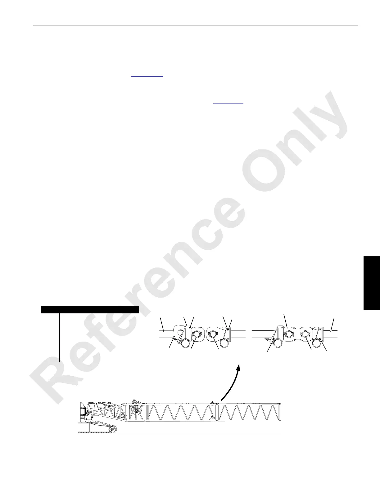
Install Boom Backstay Straps
See Figure 4-56 for the following procedure.
Starting at butt end of boom, install backstay straps in proper
sequence on boom sections according to Fixed Jib Rigging
Assembly Drawing. This step is required only if straps are not
stored on boom sections.
NOTE Backstay straps must be removed from boom
sections if jib attachment is not used.
To prevent interference between pins, heads of
boom strap pins must face outboard sides of boom;
heads of backstay strap pins must face inboard.
Connect backstay straps as follows:
1. Remove storage pins from top hole (1A, View A) in
brackets (2).
2. Store pins in bottom holes (1B, View B) in brackets (2).
3. Rotate links (3) forward and pin to adjacent straps (4,
View B).
4. Retain connecting pins (5, View B) with collars (6, View
C) and retaining pins (7).
Item Description
1A Storage Pin (strap stored)
1B Storage Pin (operation)
2 Strap Bracket (typical)
3 Link (typical)
4 Strap (typical)
5 Connecting Pin with Collar
and Retaining Pins
View B
Operation
View A
Storage
2
3
1A
1A
2
5 5
1B
1B
3
5
44

 Loading...


