SET-UP AND INSTALLATION 18000 OPERATOR MANUAL
4-26
Published 12-05-17, Control # 032-23
Install Cab Rear Platform (Current
Production)
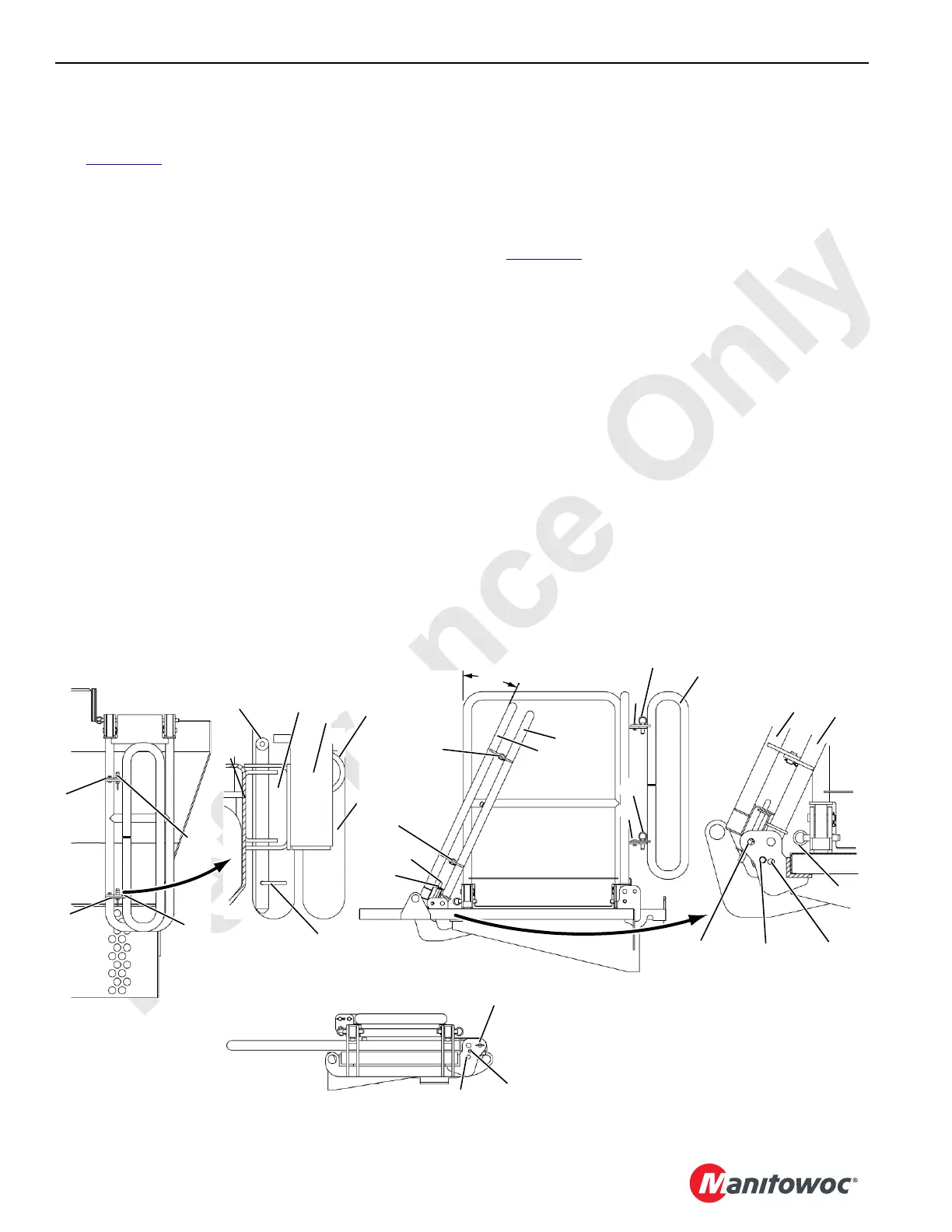
See Figure 4-17 for the following procedure.
NOTE Fork pockets are included in the platform floor for
handling by a fork truck.
1. Remove quick release pins (4) from short rear handrail
assembly (13 and 14, View A) to allow movement of
assembly about pins (9, View B).
2. Raise short rear handrail assembly (13 and 14, Views C
and D) into working position and secure by inserting
quick release pins (4, two places, View D) into working
position holes in platform weldment (5).
3. Remove quick release pins (4) from left rear (15, View A)
and long rear (16 and 17) handrails.
4. Raise left rear handrail section (15, Views A and C) into
working position and secure by inserting quick release
pins (4, View D) into working position holes in platform
weldment (5).
5. Raise long rear handrail assembly (16 and 17, Views A,
C and H) into lifting position and secure by inserting
quick release pins (4, View A) into lifting position holes
in weldment (View I).
6. Lift cab rear platform (1) into position using chain slings
from assist crane connected to four lifting holes (Views A
and C). Hooks (18, View E) in platform catwalk should
fully engage fixed pins (19) on rear of cab.
7. Remove chain slings from lifting holes in platform
assembly.
8. Level the platform’s catwalk as required after installation
with two leveling bolts (21).
Move Platforms into Working Positions
(Current Production)
See Figure 4-17 for the following procedure.
1. Remove quick release pins (10, View H) from weldments
to allow movement of short rear handrail wing (14)
around pins (6).
2. Rotate short rear handrail wing (14) 90° into working
position (View C) and secure by inserting quick release
pins into working position holes in weldments (View J).
3. Remove quick release pins (4, View I) from long rear
handrail assembly (16 and 17), carefully rotate
assembly into the working position and secure by
inserting same quick release pins into working position
holes.
4. Rotate rear handrail wing (17, View C) 90° about pins (9)
into working position and secure by inserting round bar
(11, Views G and H) into holes in weldments
5. Remove quick release pins (4, Figure 4-16, View H)
from long handrail (10), rotate to working position and
secure by inserting quick release pins (4) into working
position holes in weldment (5).
View F
View G (Detail)
View H
View I
25°
4
4
6
6
11
10
6
11
6
9
9
Working
Lifting
Shipping
10
10
FIGURE 4-17 continued
13
17
14
16
View J
Working
Lifting
Shipping
4
16
17
16
17
14
6
6
7
7
7
7