4
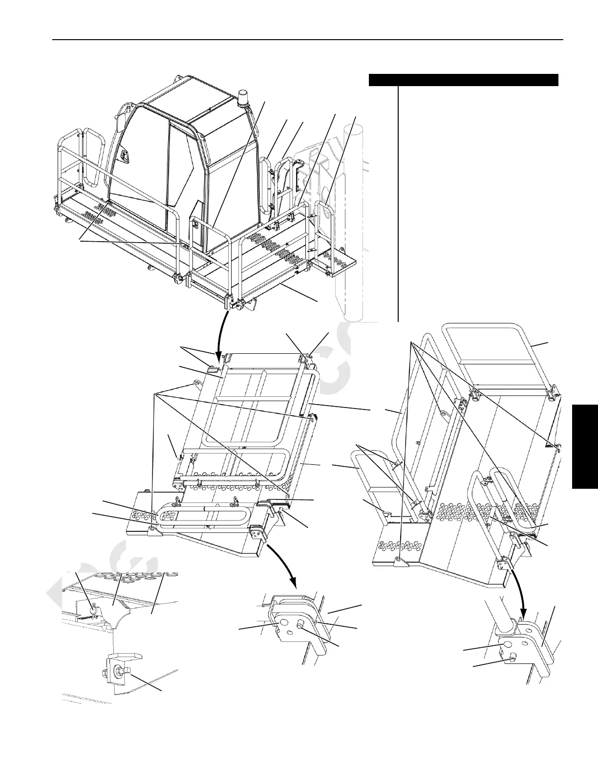
FIGURE 4-17
View A
(2 places)
LIFT
Notches
Shipping Position
4
4
11
6
7
9
5
8
12
7
9
4
2
View B
3
1
14
13
17
16
15
16
17
14
13
15
View E (2 places)
20
19
18
21
View C
(2 places)
LIFT
Working Position
4
7
9
5
9
View D
11
15
14
13
16
17
Item Description
1 Cab Rear Platform Assy
2 Hex Head Cap Screw (.5-13 X 1.00.00.65)
3 Flat Washer (.5-inch steel)
4 Quick Release Pin (15.88" dia. x 63.5" LG)
5 Platform Weldment
6 Hair Pin Cotter
7 1-Hole Pin
8 Rubber Bumper
9 Cotter Pin (1/8" dia. X 1.0" LG)
10 Quick Release Pin (15.9" dia. x 25.4" LG)
11 Round Bar (.5")
12 Slotted Head Cap Screw (6 X 16 12.9)
13 Short Rear Handrail
14 Short Rear Handrail Wing
15 Left Rear Handrail
16 Long Rear Handrail
17 Long Rear Handrail Wing
18 Hook (2 places)
19 Fixed Pin (2 places)
20 Support (2 places)
21 Leveling Bolt (2 places)
 Loading...


