Manitowoc Published 12-05-17, Control # 032-23 3-61
18000 OPERATOR MANUAL OPERATING CONTROLS AND PROCEDURES
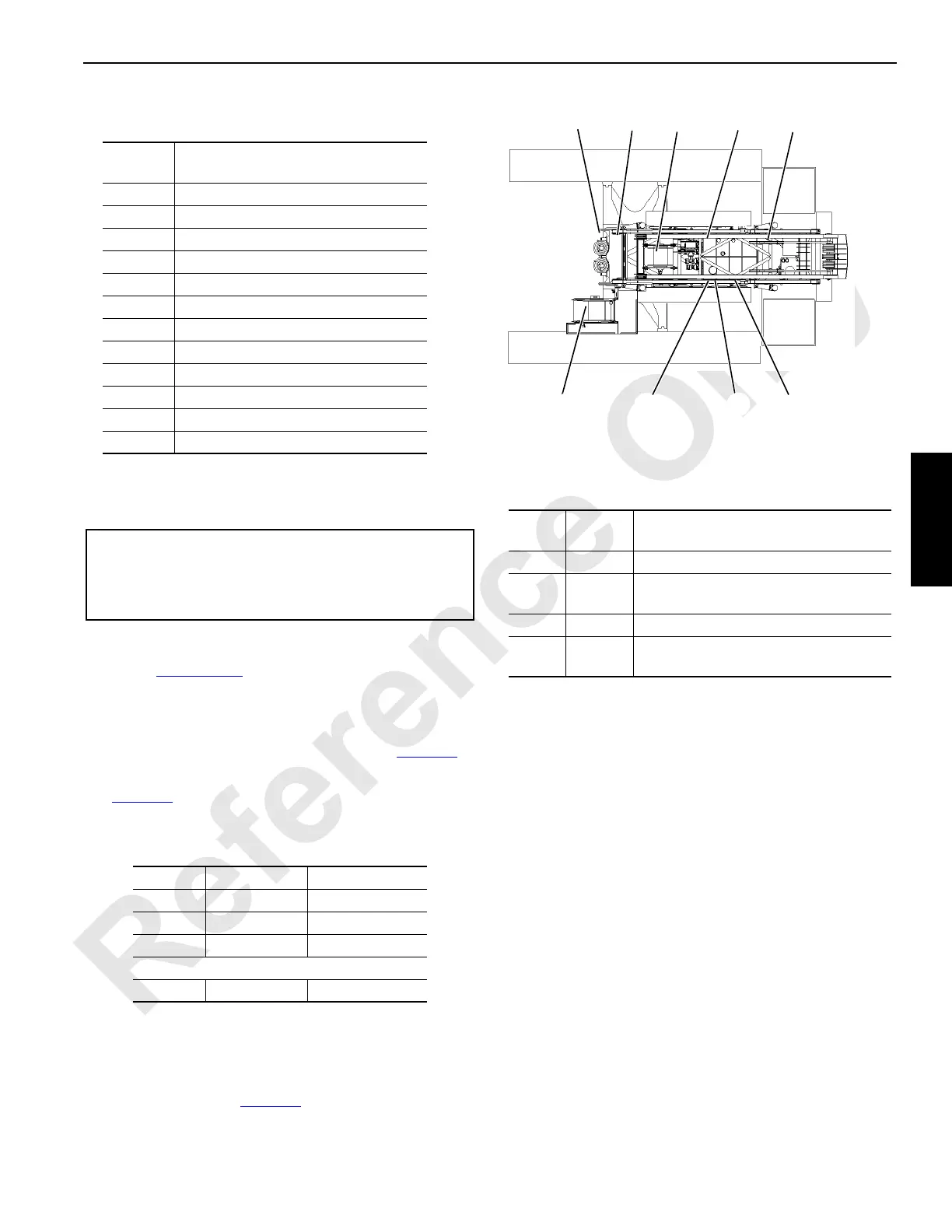
CAN (Can Bus)
The CAN screen displays digital inputs and outputs of the
master node controller. The location of crane nodes are
shown in Figure 3-43
. The CAN screen displays the
following information:
• STATUS indicates possible active communication errors
between nodes on two banks that should read 000. The
binary system status numbers are shown in Table 3-8
.
If a communication error occurs (033 in bank one) see
Table 3-8
for bank identifier numbers (node-2 and node-
7)
Table 3-8 Communication Errors
• HISTORY indicates errors since power was cycled.
Communication errors correspond to above table.
• BOOM indicates what boom nodes may be available on
the bus. Boom status should always display a number or
an error exists (see Table 3-9
).
Table 3-9 Boom Error
• ENGINE displays engine ECM bus status that is for
factory use only.
• W/L indicates what wireless receiver nodes can be
available.
- Number 1 is boom to load link
- Number 2 is remote
• PACKET ID number — Move select/confirm switch to
SELECT. Cursor appears next to Packet ID #. Scroll up
or down to desired packet number to display packet item
status.
• Digital input or digital output BANKS 1, 2, 3, and 4
• Digital input or digital output BANKS 5, 6, 7, and 8
Each individual input/output is assigned a number (identifier)
in the binary system (powers of two). The identifiers of all
inputs/outputs that are ON (active) for each bank are added
for a total of 0 – 255. The number displayed for each bank is
the sum of all identifiers that are ON in that bank. Each
possible ON/OFF combination per bank has a unique total.
FIGURE 3-43
Node Identification
Node
Number
Node
1 Master (Front Console)
2 Handles and Cab Controls
3 Drum 3 and Pressure Senders
4 Jacking, Connecting Pins, and Mast
5 Alarms, Limits and Pump Controls
6 Drums 2, 4, 5 & Adapter Frame Pins
7 Swing and Auto Lube
8 Drum 1 and Drum 6
9 MAX-ER (optional)
0 Engine
20 Boom Top (not shown)
21 Luffing or Fixed Jib Top (not shown)
In Right Side
Cab Console.
In Boom Butt
3-126
In Boom
Top or Ji b
2
3
4
9
5
6
7
8
21
20
0
BIN Node
1
STATUS 033
*PACKET ID #
BANKS 1 - 4:
BANKS 5 - 8:
000
38
55
4
HIST
0
35
000 000
BOOM 16
178 0
016
ENG
W/L
12
1
CAN
Bank 1 1 = Node 2 16 = Node 6
2 = Node 3 32 = Node 7
4 = Node 4 64 = Node 8
8 = Node 5 128 = Node 0
Bank 2 1 = Node 9 2= BIN Node
Boom
Status
Node
Number
Description
1 21 Luffing jib node with #44
821
Luffing jib node 79A or
Fixed jib node 79A
16 20 Boom top node 55A or 79A
128 20 or 21
Indicates a node is present that is not
currently identified.
 Loading...


