MANITOWOC ENGINEERING, CO.
Division of The Manitowoc Company, Inc. Manitowoc, Wisconsin 54220
OIL FLOW SWITCH
All Models
DESCRIPTION
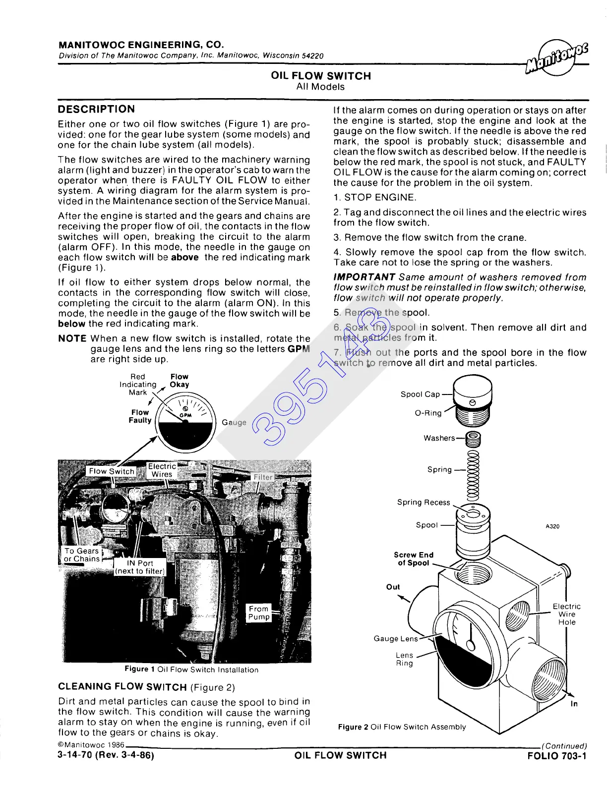
Either one or two oil flow switches (Figure 1) are pro-
vided: one for the gear lube system (some models) and
one for the chain lube system (aLl models).
The flow switches are wired to the machinery warning
alarm (light and buzzer) in the operator's cab to warn the
operator when there is FAULTY OIL FLOW to either
system. A wiring diagram for the alarm system is pro-
vided in the Maintenance section of the Service Manual.
After the engine is started and the gears and chains are
receiving the proper flow of oil, the contacts in the flow
switches will open, breaking the circuit to the alarm
(alarm OFF). In this mode, the needle in the gauge on
each flow switch will be above the red indicating mark
(Figure 1).
If oil flow to either system drops below normal, the
contacts in the corresponding flow switch will close,
completing the circuit to the alarm (alarm ON). In this
mode, the needle in the gauge of the flow switch will be
below the red indicating mark.
NOTE
When a new flow switch is installed, rotate the
gauge lens and the lens ring so the letters GPM
are right side up.
Red
Flow
Indicatina Okay
If the alarm comes on during operation or stays on after
the engine is started, stop the engine and look at the
gauge on the flow switch. If the needle is above the red
mark, the spool is probably stuck; disassemble and
clean the flow switch as described below. If the needle is
below the red mark, the spool is not stuck, and FAULTY
OIL FLOW is the cause for the alarm coming on; correct
the cause for the problem in the oil system.
1. STOP ENGINE.
2. Tag and disconnect the oil lines and the electric wires
from the flow switch.
3. Remove the flow switch from the crane.
4. Slowly remove the spool cap from the flow switch.
Take care not to lose the spring or the washers.
IMPORTANT Same amount of washers removed from
flow switch must be reinstalled in flow switch; otherwise,
flow switch will not operate properly.
5. Remove the spool.
6. Soak the spool in solvent. Then remove all dirt and
metal particles from it.
7. Flush out the ports and the spool bore in the flow
switch t,o remove all dirt and metal particles.
Spool Cap ~
Washers--~
Spring
~~
C: n ri n.~ ~ee
Figure
1 Oil Flow Switch Installation
CLEANING FLOW SWITCH (Figure 2)
Dirt and metal particles can cause the spool to bind in
the flow switch. This condition will cause the warning
alarm to stay on when the engine is running, even if oil
flow to the gears or chains is okay.
©Manitowoc 1986
Ou
Gaug~
Figure
2 Oil FIo'
(Continued)
3-14-70 (Rev. 3-4-86) OIL FLOW SWITCH FOLIO 703-1
395143