8. Thoroughly dry all parts.
9. Install a new O-ring on the spool cap if the old O-ring
is damaged.
10. Coat the spool with clean oil and slide it m
screw end
first --
into the bore.
11. Coat the washers with clean oil to hold them
together. Then insert the washers in the spool cap.
12. Place the spring in the recess in the spool,
13. Align the spring with the recess in the spool cap and
securely tighten the spool cap to the flow switch.
14. Adjust the flow switch and install it on the crane.
ADJUSTING FLOW SWITCH
NOTE The following adjustment must be done
belore
installing a new flowswitch and any time a.flow
switch has been disassembled for cleaning.
A continuity tester is required for this adjustment.
1. Remove the cover from the back of the fl0w switch.
2. Connect the continuity tester to the terminals in the
flow switch (Figure 3)~ The tester should show
current
flow (alarm would be ON indicating no oil flow).
NOTE Make sure the reed is installed as shown in (Fig-
ure 3). The end of the reed from which the wires
come out must be toward the spool cap end of
the flow switch.
Continuity Tester
Wire Indicating
Setscrew Terminals Current Flow
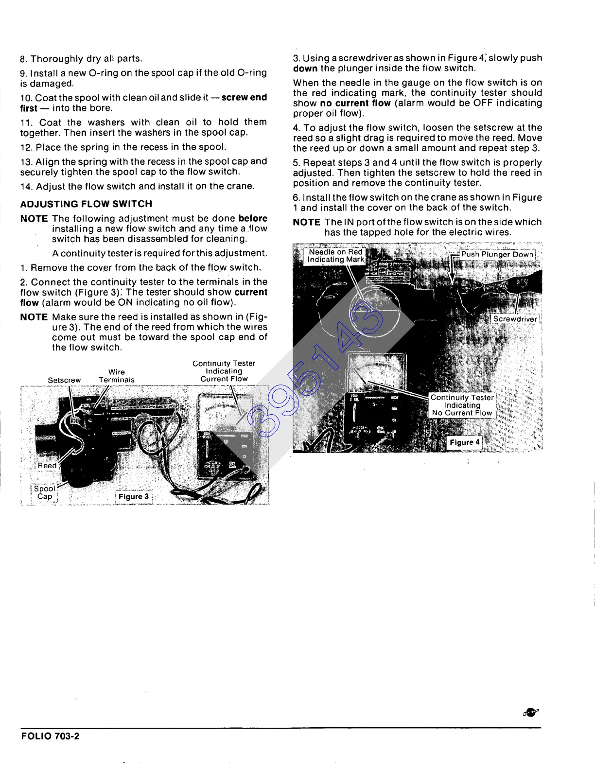
3. Using a screwdriver as shown in Figure 4; slowly push
down the plunger inside the flow switch.
When the needle in the gauge on the flow switch is on
the red indicating mark, the continuity tester should
show
no current
flow (alarm would be OFF indicating
proper oil flow).
4. To adjust the flow switch, loosen the setscrew at the
reed so a slight drag is required to move the reed. Move
the reed up or down a small amount and repeat step 3.
5. Repeat steps 3 and 4 until the flow switch is properly
adjusted. Then tighten the setscrew to hold the reed in
position and remove the continuity tester.
6. Install the flow switch on the crane as shown in Figure
1 and install the cover on the back of the switch.
NOTE The IN port of the flow switch is on the side which
has the tapped hole for the electric wires.
FOLIO 703-2
395143