MANITOWOC ENGINEERING, CO.
Division of The Manitowoc Company, Inc. Manitowoc, Wisconsin 54220
ELECTRIC GAUGES
All Models
GENERAL
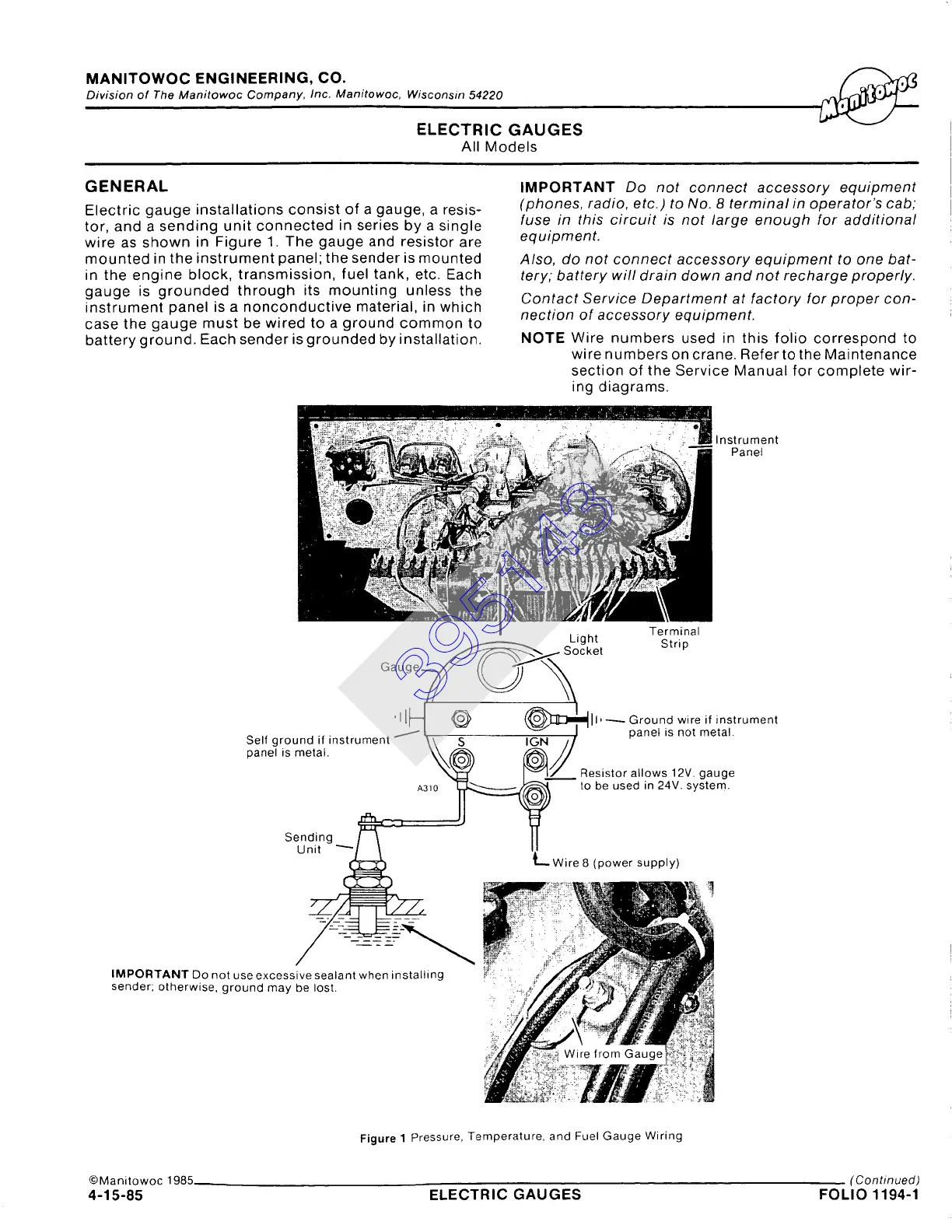
Electric gauge installations consist of a gauge, a resis-
tor, and a sending unit connected in series by a single
wire as shown in Figure 1. The gauge and resistor are
mounted in the instrument panel; the sender is mounted
in the engine block, transmission, fuel tank, etc. Each
gauge is grounded through its mounting unless the
instrument panel is a nonconductive material, in which
case the gauge must be wired to a ground common to
battery ground. Each sender is grounded by installation.
IMPORTANT
Do not connect accessory equipment
(phones, radio, etc.) to No. 8 terminal in operator's cab;
fuse in this circuit is not large enough for additional
equipment.
Also, do not connect accessory equipment to one bat-
tery; battery will drain down and not recharge properly.
Contact Service Department at factory for proper con-
nection of accessory equipment.
NOTE Wire numbers used in this folio correspond to
wire numbers on crane. RefertotheMaintenance
section of the Service Manual for complete wir-
ing diagrams.
Instrument
Panel
sLog~e[ t Strip
G a u g e ~~"'~'I~--~
I . I ,
' [H ~ ~11 ~ Ground wire if instrument
Self ground if instrument ~ \\ SIgN // panel ,s not metal.
panel is metal. ~--~ L~----~//
A3,0 e
Se~diitg ..._~3-~--= A31°~Wire8(powersupply)" " "
IMPORTANT [3o not use excessive sealant when
installing
sender; otherwise, ground may be lost.
Figure 1 Pressure, Temperature. and Fuel Gauge Wiring
©Manitowoc 1985
(Continued)
4-15-85 ELECTRIC GAUGES FOLIO 1194-1
395143