POWER SOURCE
Pressure, Temperature, and Fuel Gauges
All gauges except the ammeter receive power through a
normally-open pressure switch on the engine and a
normally-open relay on the junction box at the engine
(see Figure 2).
When engine oil pressure is 4 psi or higher (engine must
be running), the engine oil pressure switch closes,
allowing current in wire 5C to flow through wire 8A to the
relay. Current in wire 8A flows to ground at the relay,
causing the relay to close. With the relay closed, current
in wire 5B flows through wire 8 and a fuse in the junction
box to the gauges.
Normally-Open
Relay on Junction
Box at Engine
lire 8
r to gauge
Wire 5B ;Ih fuse in
(power to r~ :ion box)
Wire 8A Relay
(from press. Ground
switch)
Figure
2 Power Supply Wiring for Gauges
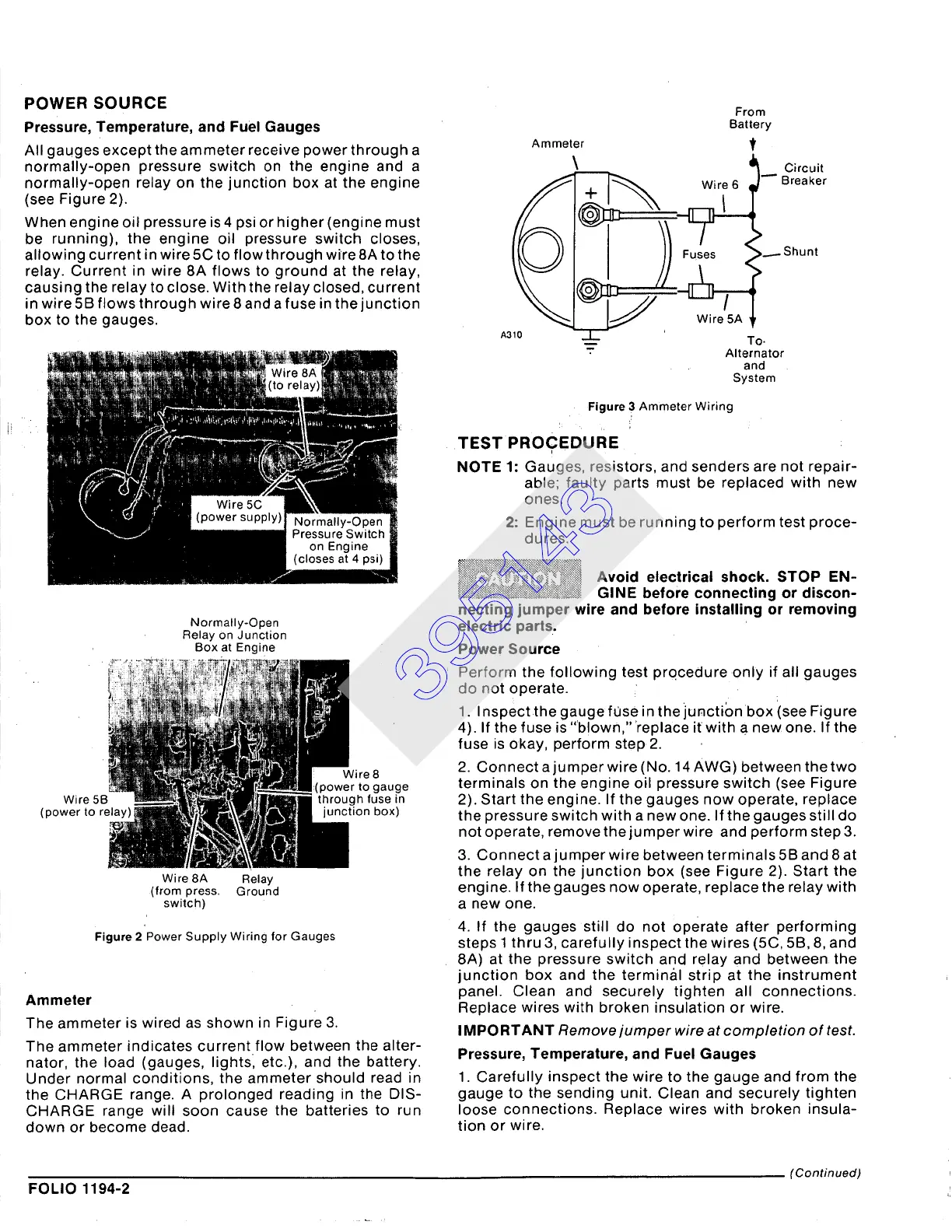
Ammeter
The ammeter is wired as shown in Figure 3.
The ammeter indicates current flow between the alter-
nator, the load (gauges, lightsl etc.), and the battery.
Under normal conditions, the ammeter should read in
the CHARGE range. A prolonged reading in the DIS-
CHARGE range will soon cause the batteries to run
down or become dead.
Ammeter
\
A310
, Figure 3 Ammeter Wiring
TEST PROCEDURE
From
Battery
t
Wire6 1--BC~C~etr
---- To.
- Alternator
and
System
NOTE 1: Gauges, resistors, and senders are not repair-
able; faulty parts must be replaced with new
ones.
2: Engine must be running to perform test proce-
dures.
,:~.~.~.~:~.~
Avoid electrical
shock. STOP EN-
~~i~i GINE
before connecting or discon-
necting jumper wire and before installing or removing
electric parts..
Power Source
Perform the following test pro.cedure only if all gauges
do not operate.
1. Inspectthe gauge fuse in the iunction box isee Figure
4). If the fuse is '"blown," 'replace it with a new one. If the
fuse is okay, perform step 2.
2. Connect ajumperwire(No. 14 AWG) between the two
terminals on the engine oil pressure switch (see Figure
2). Start the engine. If the gauges now operate, replace
the pressure switch with a new one. If the gauges still do
not operate, removethejumper wire and perform step3.
3. Connect a jumper wire between terminals 5B and 8 at
the relay on the junction box (see Figure 2). Start the
engine. If the gauges now operate, replace the relay with
a new one.
4. If the gauges still do not operate after performing
steps 1 thru 3, carefully inspect the wires (5C, 5B, 8, and
8A) at the pressure switch and relay and between, the
junction box and the terminal strip at the instrument
panel. Clean and securely tighten all connections.
Replace wires with broken insulation or wire.
IMPORTANT Remove jumper wire at completion of test.
Pressure, Temperature, and Fuel Gauges
1. Carefully inspect the wire to the gauge and from the
gauge to the sending unit. Clean and securely tighten
loose connections. Replace wires with broken insula-
tion or wire.
(Continued)
FOLIO 1194-2
395143