Wire 6
Wire 8 to
Terminal Strip
at Instrument Panel
Wire 6
from Battery
Ammeter
Shunt
Wire
5B
to Relay
Wire 5A
Wire 8
from Relay
Wire 5
from Alternator
Ammeter
Fuses
Gauge
Fuse
A3t0
Resistor
/
Voltmeter
Figure
5 Resistor
Figure
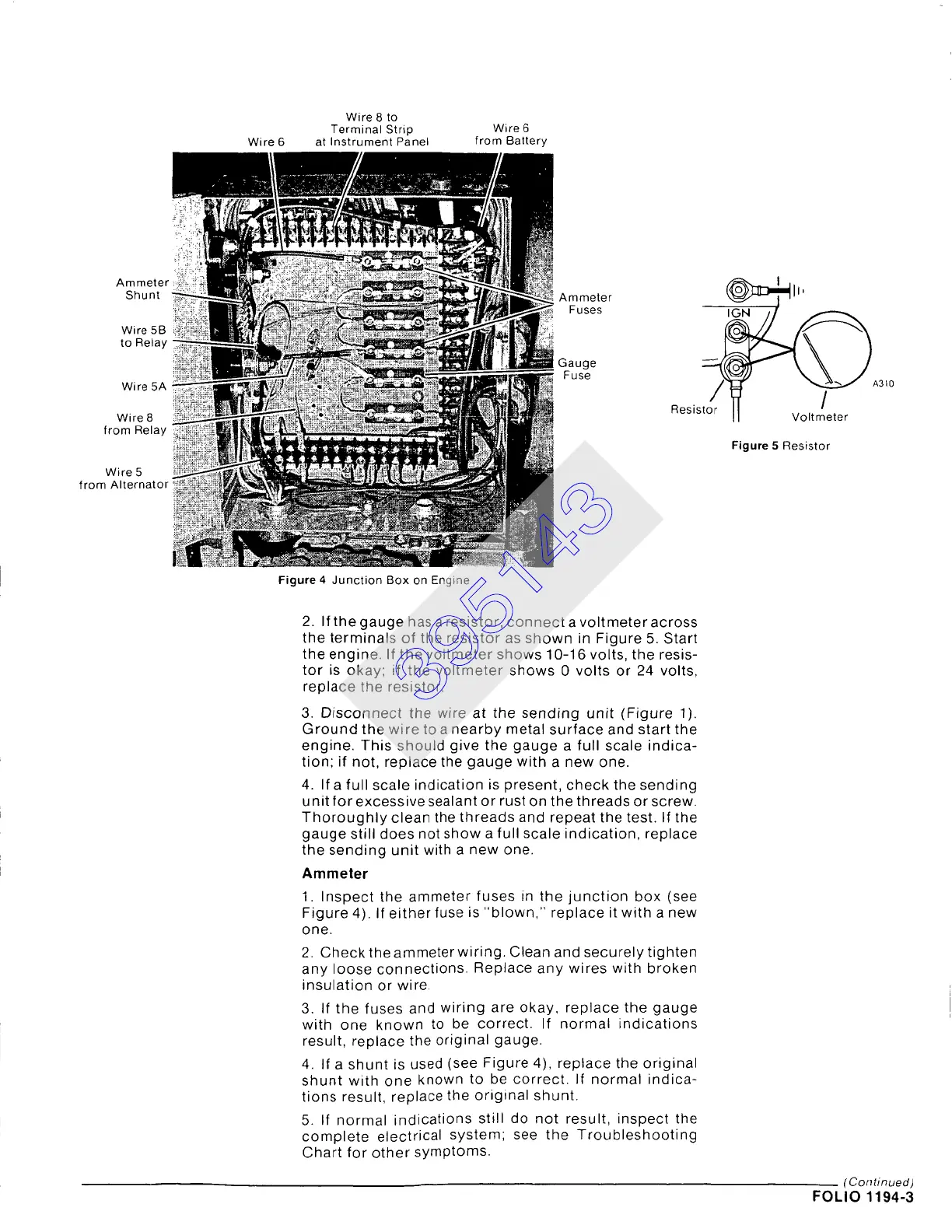
4 Junction Box on Engine
2. If the gauge has a resistor, connect a voltmeter across
the terminals of the resistor as shown in Figure 5. Start
the engine. If the voltmeter shows 10-16 volts, the resis-
tor is okay; if the voltmeter shows 0 volts or 24 volts,
replace the resistor.
3. Disconnect the wire at the sending unit (Figure 1).
Ground the wire to a nearby metal surface and start the
engine. This should give the gauge a full scale indica-
tion; if not, replace the gauge with a new one.
4. If a full scale indication is present, check the sending
unit for excessive sealant or rust on the threads or screw.
Thoroughly clean the threads and repeat the test. If the
gauge still does not show a full scale indication, replace
the sending unit with a new one.
Ammeter
1. Inspect the ammeter fuses in the junction box (see
Figure 4). If either fuse is "blown," replace it with a new
one.
2. Check the ammeter wiring. Clean and securely tighten
any loose connections. Replace any wires with broken
insulation or wire.
3. If the fuses and wiring are okay, replace the gauge
with one known to be correct. If normal indications
result, replace the original gauge.
4. If a shunt is used (see Figure 4), replace the original
shunt with one known to be correct. If normal indica-
tions result, replace the original shunt.
5. If normal indications still do not result, inspect the
complete electrical system; see the Troubleshooting
Chart for other symptoms.
(Continued)
FOLIO 1194-3
395143