MANITOWOC ENGINEERING CO.
division of The Manitowoc Company, Inc. Manitowoc, Wisconsin 54220
TRANSMIssION CASE LUBRICATION SYSTEM
ALL MODELS
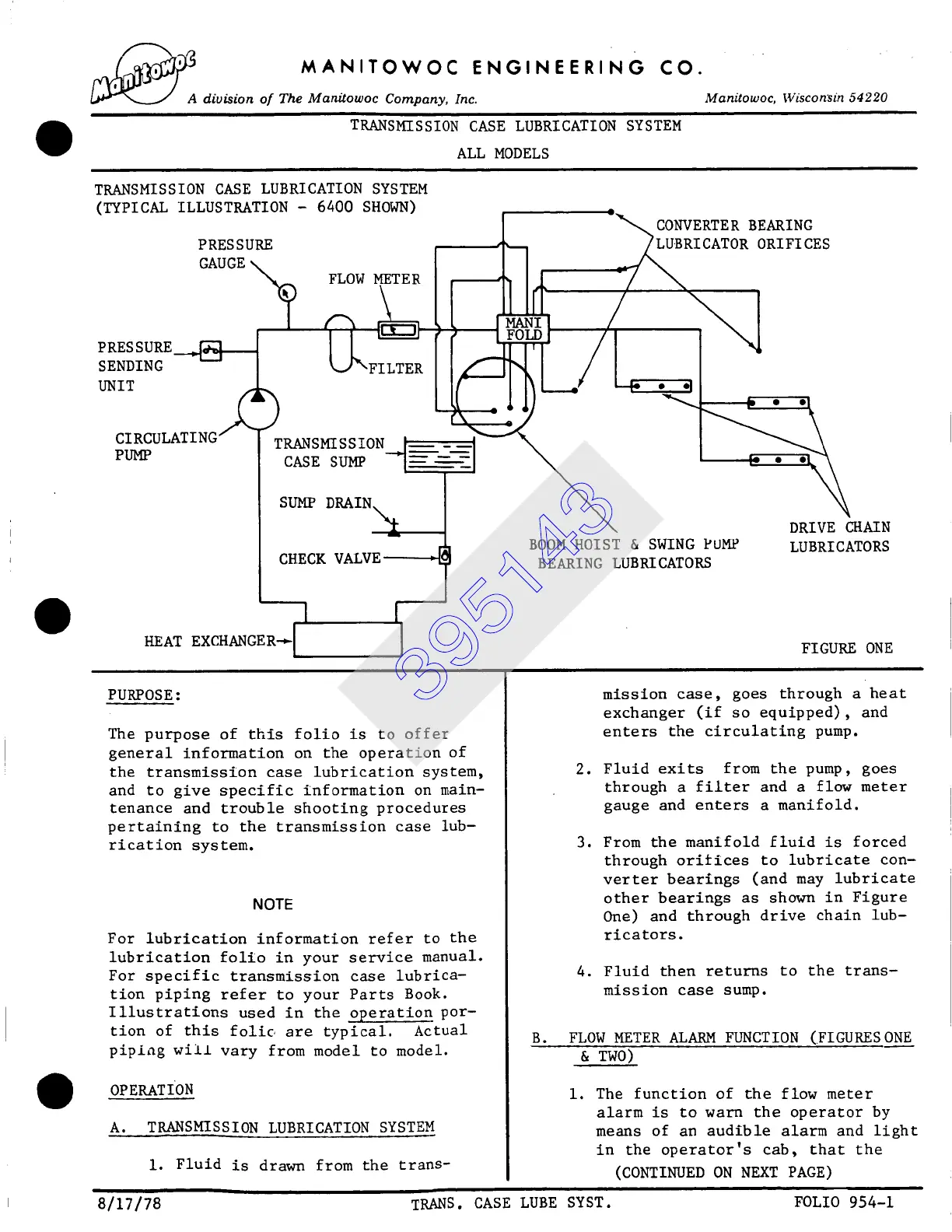
TRANSMISSION CASE LUBRICATION SYSTEM
0 00
SENDING
ORIFICES
)
T s ssloN
CASE SUMP ---
SUMP DRAIN~
DRIVE CHAIN
CHECK VALVE ~[ BOOM HOIST & SWING PUMP LUBRICATORS
L BEARING LUBRICATORS
FIGURE ONE
PURPOSE:
The purpose of this folio is to offer
general information on the operation of
the transmission case lubrication system,
and to give specific information on main-
tenance and trouble shooting procedures
pertaining to the transmission case lub-
rication system.
NOTE
For lubrication information refer to the
lubrication folio in your service manual.
For specific transmission case lubrica-
tion piping refer to your Parts Book.
Illustrations used in the operation por-
tion of this folic are typical. Actual
piping wii± vary from model to model.
OPERATION
A. TRANSMISSION LUBRICATION SYSTEM
i. Fluid is drawn from the trans-
mission case, goes through a heat
exchanger (if so equipped), and
enters the circulating pump.
2. Fluid exits from the pump, goes
through a filter and a flow meter
gauge and enters a manifold.
3. From the manifold fluid is forced
through orilices to lubricate con-
verter bearings (and may lubricate
other bearings as shown in Figure
One) and through drive chain lub-
ricators.
4. Fluid then returns to the trans-
mission case sump.
B. FLOW METER ALARM FUNCTION (.FIGURESONE
TWO)
i. The function of the flow meter
alarm is to warn the operator by
means of an audible alarm and light
in the operator's cab, that the
(CONTINUED ON NEXT PAGE)
8/17/78 TRANS. CASE LUBE SYST. FOLIO 954-1
395143