MANITOWOC ENGINEERING, CO.
Division of The Manitowoc Company, Inc. Manitowoc, Wisconsin 54220
ROTATING BED SUMP CIRCULATING OIL SYSTEM
3000 -- 4600 Series-4/5
CONTENTS Page
System Operation ............................... 1
Pressure Gauge Operation ....................... 2
Flow Switch Operation ........................... 2
Maintenance .................................... 2
Every 8 Hours ................................. 2
Every 200 Hours ............................... 3
Every 2000 Hours .............................. 3-4
Relief Valve Adjustment .......................... 4
Cleaning Relief Valve ............................ 5
Troubleshooting Guide .......................... 5
NOTE
The illustrations and photos used in this folio are
for identification purposes only; they do not
depict any one model. The location of compo-
nents and the items which are lubricated varies
from model to model; refer to your parts manual
for the exact piping arrangement on your crane.
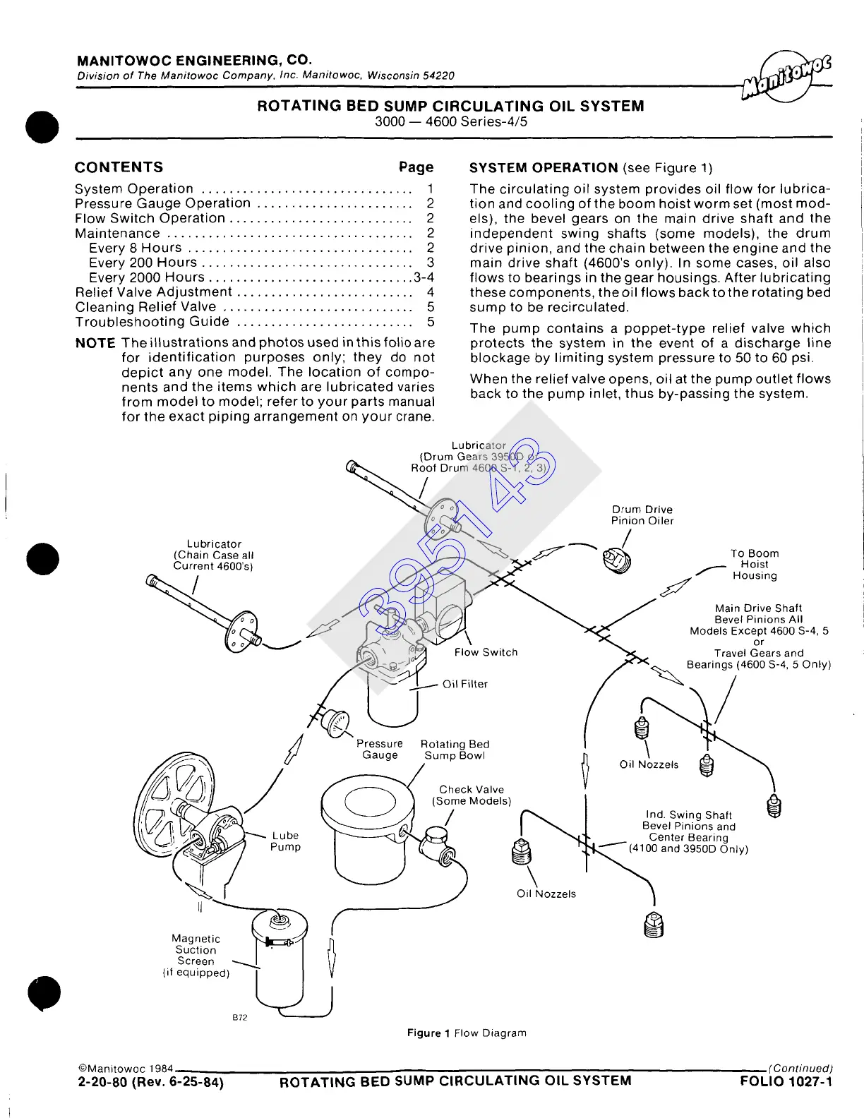
SYSTEM OPERATION
(see Figure 1)
The circulating oil system provides oil flow for lubrica-
tion and cooling of the boom hoist worm set (most mod-
els), the bevel gears on the main drive shaft and the
independent swing shafts (some models), the drum
drive pinion, and the chain between the engine and the
main drive shaft (4600's only). In some cases, oil also
flows to bearings in the gear housings. After lubricating
these components, the oil flows back to the rotating bed
sump to be recirculated.
The pump contains a poppet-type relief valve which
protects the system in the event of a discharge line
blockage by limiting system pressure to 50 to 60 psi.
When the relief valve opens, oil at the pump outlet flows
back to the pump inlet, thus by-passing the system.
Screen ~ I
(if equipped) L~
B72
Lubricator
(Drum Gears 3950D or
4600 S-1,2, 3)
Drum Drive
Pinion Oiler
Lubricator ~~;:~ ~ ~ T:H!!s!:
(Chain Case all
Current 4600's) ~
S
~ / Main Drive Shaft
~ , 7/-.y41 ~
.
_/ Bevel Pinions All
.~ k.~ ~\ ~ Models Except 4600 S-4, 5
~l~'~ ~"-""~ ~'~"FIo~w Switch ~ Travel Gearsand
~.~.~_.~ I /,,,,,~___.~ Bearings (4600 S-4,5Only)
J Pressure Rotating Bed I \ ['"
~ i ~ / Gauge SumpBowl h ' .Z~ ~
" ~% / It oi, .ozze~s ~
",~
f/---~---...~ ~ Check Valve V -
~ ~ (Some Models) I [~}
I\ ~-~ /I / ~ I Ind. Swing Shaft ~;~
"~~
!/ ,'-'-,/ I ~ / Bevel Pinions and
Lube ~ ~ ~ ,"~,t,,-~4 .L' "~1,, Center Bearing
0Oa 03 OOOn ,
f 0
J
Figure 1 Flow Diagram
©Manitowoc 1984 ,.,
(Continued)
2-20-80 (Rev. 6-25-84) ROTATING BED SUMP CIRCULATING OIL SYSTEM FOLIO 1027-1
395143