tvfanitowoc Engineering Co.
PRESSURE GAUGE OPERATION (all cranes)
The normal operating pressure for the circulating oil
system is 10 to 25 psi, depending on temperature. Pres-
sure is shown on a gauge mounted at the pump, at the
filter, or in the operator's cab.
FLOW SWITCH
OPERATION
(current production cranes)
The flow switch is wired to a fault light and alarm in the
operator's cab. Refer to the Operator's Guide for a list of
faults that will turn on the light and alarm.
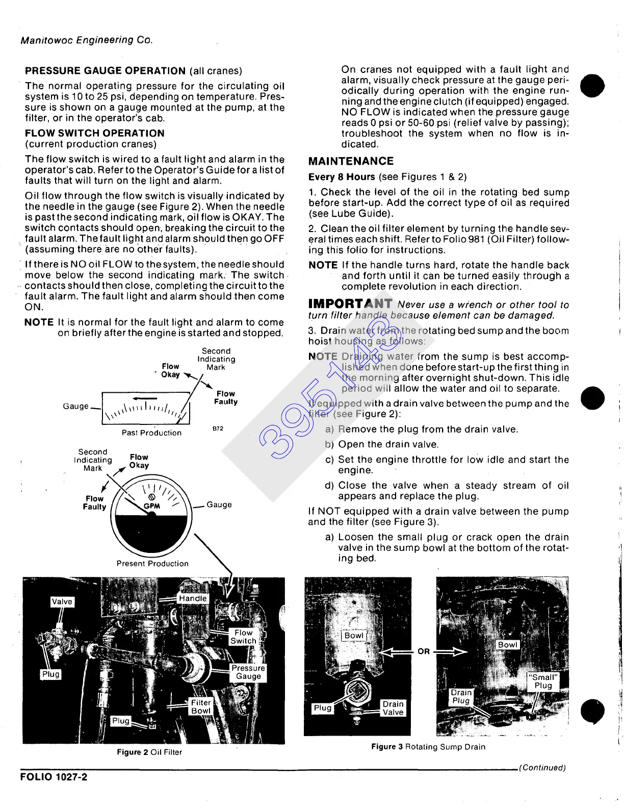
Oil flow through the flow switch is visually indicated by
the needle in the gauge (see Figure 2). When the needle
is past the second indicating mark, oil flow is OKAY• The
switch contacts should open, breaking the circuit to the
fault alarm. The fault light and alarm should then go OFF
(assuming there are no other faults).
If there is NO oil FLOW to the system, the needle should
move below the second indicating mark, The switch
contacts should then close, completing the circuit to the
faUlt alarm• The fault light and alarm should then come
ON.
NOTE It is normal for the fault light and alarm to come
on briefly after the engine is started and stopped•
Second
Indicating
Flow
Mark
" Okay "~r,~/,~,
• Flow
Faulty
I x``
B72
Past Production
Second
Indicating
Flow
..... t~ k~iv
Figure 2 Oil Filter
On cranes not equipped with a fault light and
alarm, visually check pressure at the gauge peri-
odically during operation with the engine run-
ning and the engine clutch (if equipped) engaged.
NO FLOW is indicated when the pressure gauge
reads 0 psi or 50-60 psi (relief valve by passing);
troubleshoot the system when no flow is in-
dicated.
MAINTENANCE
Every 8 Hours
(see Figures
1 & 2)
1• Check the level of the oil in the rotating bed sump
before start-up. Add the correct type of oil as required
(see Lube Guide)•
2. Clean the oil filter element by turning the handle sev-
eral times each shift. Refer to Folio 981 (O.il Filter) follow-
ing this folio for instructions.
NOTE If the handle turns hard, rotate the handle back
and forth until it can be turned easily through a
complete revolution in each direction.
IMPORTANT
Never use a wrench or other tool to
turn filter handle because element can be damaged.
3. Drain water from the rotating bed sump and the boom
hoist housing as follows:
NOTE Draining water from the sump is best accomp-
lished when done before start-up the first thing in
the morning after overnight shut-down. This idle
period will allow the water and oil to separate.
If equipped with a drain valve between the pump and the
filter (see Figure 2):
a) Remove the plug from the drain valve.
b) Open the drain valve.
c) Set the engine throttle for low idle and start the
engine.
d) Close the valve when a steady stream of oil
appears and replace the plug.
If NOT equipped with a drain valve between the pump
and the filter (see Figure 3).
a) Loosen the small plug or crack open the drain
valve in the sump bowl at the bottom of the rotat-
ing bed.
OR
Figure
3 Rotating Sump Drain
(Continued)
FOLIO 1027-2
395143