Manitowoc Engineering Co.
b) When a steady stream of oil appears, securely
retighten the plug or close the valve.
Also drain the water from the boom hoist housing (see
Figure 4) as follows:
a) Loosen the drain plug or crack open the drain
valve in the boom hoist housing.
b) When a steady stream of oil appears, securely
retighten the plug or close the valve.
Figure
4 Boom Hoist Housing Drain
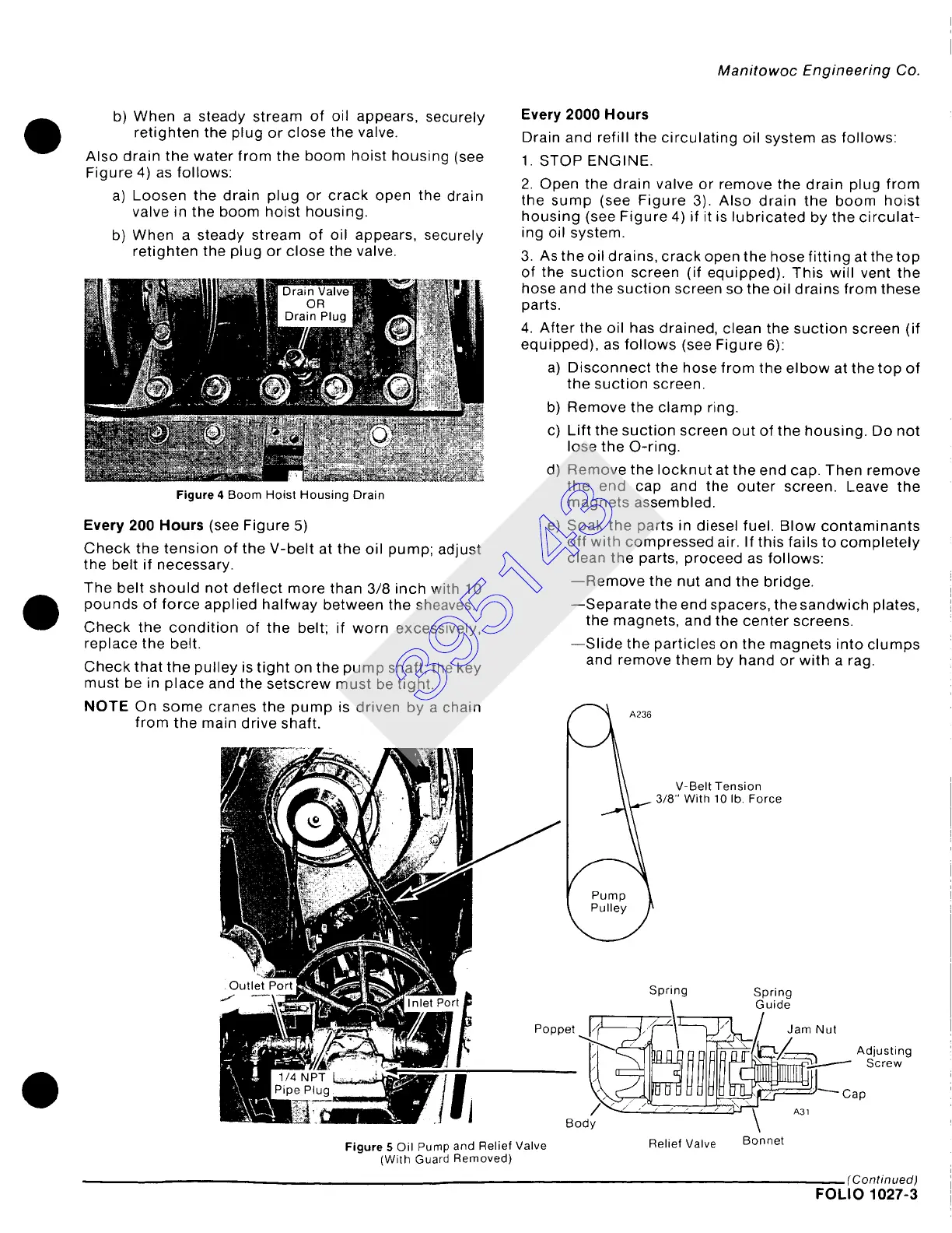
Every 200 Hours
(see Figure 5)
Check the tension of the V-belt at the oil pump; adjust
the belt if necessary.
The belt should not deflect more than 3/8 inch with 10
pounds of force applied halfway between the sheaves.
Check the condition of the belt; if worn excessively,
replace the belt.
Check that the pulley is tight on the pump shaft; the key
must be in place and the setscrew must be tight.
NOTE On some cranes the pump is driven by a chain
from the main drive shaft.
Every 2000 Hours
Drain and refill the circulating oil system as follows:
1. STOP ENGINE.
2. Open the drain valve or remove the drain plug from
the sump (see Figure 3). Also drain the boom hoist
housing (see Figure 4) if it is lubricated by the circulat-
ing oil system.
3. As the oil drains, crack open the hose fitting at the top
of the suction screen (if equipped). This will vent the
hose and the suction screen so the oil drains from these
parts.
4. After the oil has drained, clean the suction screen (if
equipped), as follows (see Figure 6):
a) Disconnect the hose from the elbow at the top of
the suction screen.
b) Remove the clamp ring.
c) Lift the suction screen out of the housing. Do not
lose the O-ring.
d) Remove the Iocknut at the end cap. Then remove
the end cap and the outer screen. Leave the
magnets assembled.
e) Soak the parts in diesel fuel. Blow contaminants
off with compressed air. If this fails to completely
clean the parts, proceed as follows:
--Remove the nut and the bridge.
--Separate the end spacers, the sandwich plates,
the magnets, and the center screens.
--Slide the particles on the magnets into clumps
and remove them by hand or with a rag.
V-Belt Tension
3/8" With 10 lb. Force
Figure
5 Oil Pump and Relief Valve
(With Guard Removed)
Spring Spring
\ Guide
,e t ~.~./~L~ ~.~L~/~ / Jam Nut
-- Bod~U U U U U IU>~J...~ Cap
Relief Valve Bonnet
(Continued)
FOLIO 1027-3
395143