Manitowoc Engineering Co.
IMPORTANT
Handle magnets with care to avoid
cracking or breaking them.
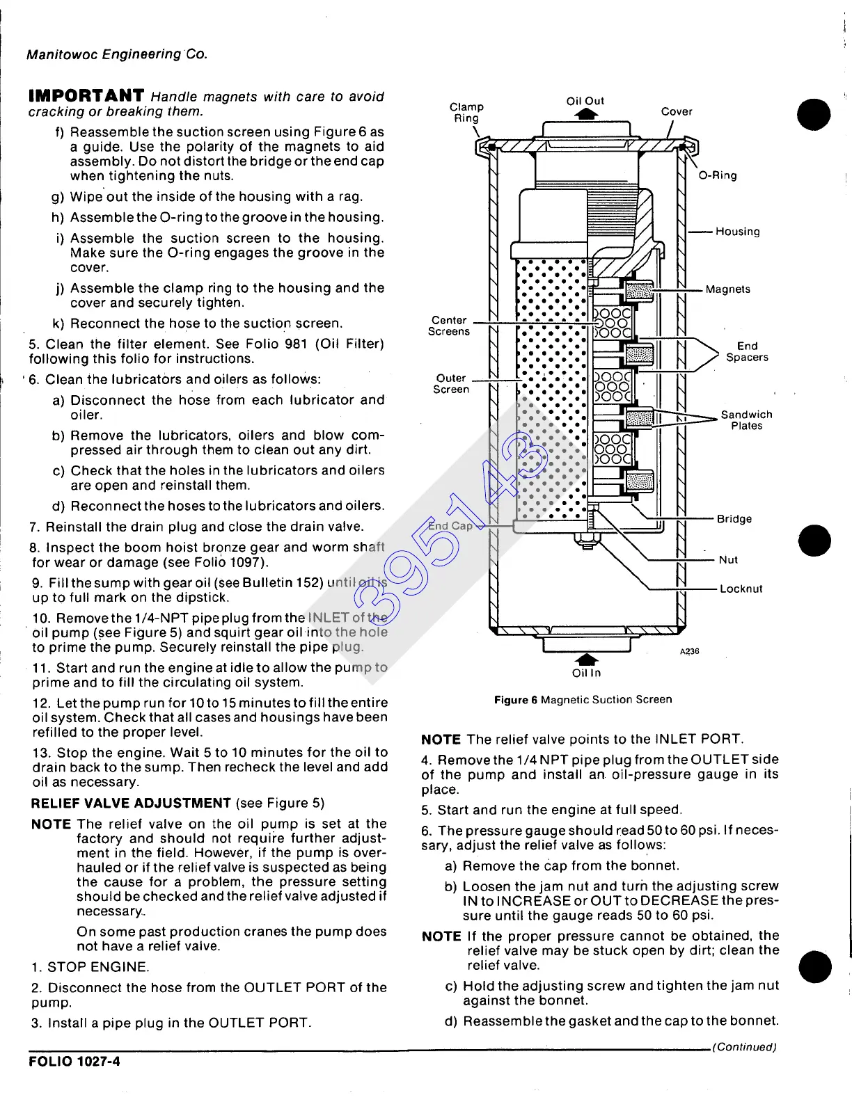
f) Reassemble the suction screen using Figure6 as
a guide. Use the polarity of the magnets to aid
assembly. Do not distort the bridge or the end cap
when tightening the nuts.
g) Wipeout the inside of the housing with a rag.
h) Assemble the O-ring to the groove in the housing.
i) Assemble the suction screen to the housing.
Make sure the O-ring engages the groove in the
cover.
j) Assemble the clamp ring to the housing and the
cover and securely tighten.
k) Reconnect the hose to the suction screen.
5. Clean the filter element. See Folio 981 (Oil Filter)
following this folio for instructions.
' 6. Clean the lubricators and oilers as folloWs:
a) Disconnect the hose from each lubricator and
oiler.
b) Remove the lubricators, oilers and blow com-
pressed air through them to clean out any dirt.
c) Check that the holes in the lubricators and oilers
are open and reinstall them.
d) Reconnect the hoses to the lubricators and oilers.
7. Reinstall the drain plug and close the drain valve.
8. Inspect the boom hoist bronze gear and worm shaft
for wear or damage (see Foli() 1097).
9. Fill the sump with gear oil (see Bulletin 152) until oil is
up to full mark on the dipstick.
10. Removethe 1/4-NPT pipe plug from the INLET of the
oil pump (.see Figure 5) and squirt gear oil into the hole
to prime the pump. Securely reinstall the pipe plug.
11. Start and run the engine at idle to allow the pump to
prime and to fill the circulating oil system.
12. Let thepump run for 10to 15 minutes to fill the entire
oil system. Check that all cases and housings have been
refilled to the proper level.
13. Stop the engine. Wait 5 to 10 minutes for the oil to
drain back to the sump. Then recheck the level and add
oil as necessary.
RELIEF VALVE ADJUSTMENT (see Figure 5)
NOTE The relief valve on the oil pump is set at the
factory and should not requii'e further adjust-
ment in the field. However, if the pump is over-
hauled or if the relief valve is suspected as being
the cause for a problem, the pressure setting
should be checked and the relief valve adjusted if
necessary.
On some past production cranes the pump does
not have a relief valve.
1. STOP ENGINE.
2. Disconnect the hose from the OUTLET PORT of the
pump.
3. Install a pipe plug in the OUTLET PORT.
FOLIO 1027-4
Clamp
Ring
Center
Screens
Outer
Screen
End Cap
Oil Out
A__
f
~O°O0000
~o00OeOo
~O00OO00
boOlOo0 O
J OlOaO 8
~oOoUeOo
JoOoOoOl
JO000oOo
.:.;.:.
,ooeo
~O0oOoOo
~oOoO000
~oOoOeO0
~oOoOoOo
~oOoO00o
~O000oO0
boOoOoO o
bOOOO00 o
IOO0000 o
)O°O°O°O
•
4b-
Oil In
Cover
I A236
Figure 6 Magnetic Suction Screen
ing
tousing
kgnets
End
Spacers
Sandwich
Plates
3ridge
Nut
Locknut
NOTE The relief valve points to the INLET PORT.
4. Remove the 1/4 N PT pipe plug from the OUTLET side
of the pump and install an oil-pressure gauge in its
place.
5. Start and run the engine at full speed.
6. The pressure gauge should [ead 50 to 60 psi. If neces-
sary, adjust the relief valve as follows:
a) Remove the Cap from the bonnet.
b) Loosen the jam nut and turn the adjusting screw
IN to INCREASE or OUT to DECREASE the pres-
sure until the gauge reads 50 to 60 psi.
NOTE If the proper pressure cannot be obtained, the
relief valve may be stuck open by dirt; clean the
relief valve.
c) Hold the adjusting screw and tighten the jam nut
against the bonnet.
d) Reassemblethe gasket and the cap to the bonnet.
(Continued)
395143