MANITOWOC ENGINEERING
division o[ The Manitowoc Company, Inc.
CO.
Manitowoc, Wisconsin 54220
BOOM ASSEMBLY -- GENERAL INFORMATION
ALL MODELS
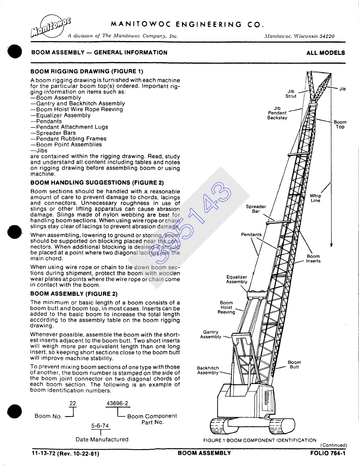
BOOM RIGGING DRAWING (FIGURE 1)
A boom rigging drawing is furnished with each machine
for the particular boom top(s) ordered. Important rig-
ging information on items such as:
--Boom Assembly
--Gantry and Backhitch Assembly
--Boom Hoist Wire Rope Reeving
--Equalizer Assembly
--Pendants
--Pendant Attachment Lugs
--Spreader Bars
--Pendant Rubbing Frames
--Boom Point Assemblies
--Jibs
are contained within the rigging drawing. Read, study
and understand all content including tables and notes
on rigging drawing before assembling boom or using
machine.
BOOM HANDLING SUGGESTIONS (FIGURE 2)
Boom sections should be handled with a reasonable
amount of care to prevent damage to chords, lacings
and connectors. Unnecessary roughness in use of
slings or other lifting apparatus can cause abrasion
damage. Slings made of nylon webbing are best for
handling boom sections. When using wire rope or chain
slings stay clear of lacings to prevent abrasion damage.
When assembling, lowering to ground or storing, boom
should be supported on blocking placed near the con-
nectors. When additional blocking is desired it should
be placed at a point where two diagonal lacings join the
main chord.
When using wire rope or chain to tie down boom sec-
tions during shipment, protect the boom with wooden
wear plates at points where the wire rope or chain come
in contact with the boom.
BOOM ASSEMBLY (FIGURE 2)
The minimum or basic length of a boom consists of a
boom butt and boom top, in most cases. Inserts can be
added to the basic boom to increase the total length
according to the assembly table on the boom rigging
drawing.
Whenever possible, assemble the boom with the short-
est inserts adjacent to the boom butt. Two short inserts
will weigh more per equivalent length than one long
insert, so keeping short sections close to the boom butt
will improve machine stability.
To prevent mixing boom sections of one type with those
of another, the boom number is stamped on the side of
the boom joint connector on two diagonal chords of
each boom section. The following is an example of
boom identification numbers.
Boom No.
22 43696-2
-[- L Boom Component
Part No.
5-6-74
I
Date Manufactured
Jib
Strut
Jib
Pendant
Backstay
Spreader
Bar
Whip
Line
Pendant,
Boom
Inserts
Equalizer
Assembly
Boom
Hoist
Reevin(
Gantry
Assembh/
Backhitch
Assembry~
Boom
Butt
FIGURE 1 BOOM COMPONENT IDENTIFICATION
Jib
Boom
Top
(Continued)
11-13-72 (Rev. 10-22-81) BOOM ASSEMBLY FOLIO 764-1
395143
 Loading...


