Manitowoc Engineering Co.
Remember, when selecting boom sections for a particu-
lar boom length always follow the assembly table on the
rigging drawing.
WARNING
Avoid Injury to personnel and
damage to crane and property. NEVER --
Work under the boom.
Assemble or disassemble any boom section with-
out first supporting BOTH SIDES of the boom with
blocking at that point.
PENDANTS (FIGURE 3 AND 4)
The top side of each pendant is marked with a line
running the full length of the pendant. It is important
when installing pendants, that this line NOT BE
TWISTED during pendant installation. Should this line
not be straight, twist pendant so wire rope is tighter and
line is straight,
GANTRY AND BACKHITCH ASSEMBLY
Whenever possible operate with the gantry pinned in its
highest position. This reduces the stress in the boom
hoisting equipment Which means longer life and added
safety for your. equipment.
WARNING
Before raising or lowering gantry,
equalizer must be pinned to boom at equalizer
attaching rails or damage to lacings can occur.
Refer to individual gantry assembly drawing or folio (if
furnished) for detailed information on raising and lower-
ing gantry.
BOOM HOIST WIRE ROPE REEVING
Always use appropriate type and length of wire rope as
called for on the boom rigging drawing when reeving
boom hoist drums to equalizer assembly.
EQUALIZER ASSEMBLY
Attachment of pendants to equalizer, and equalizer to
attaching rails can vary from oneapplication to another
on the same mode/machine. Refer toindividual equal-
izer assembly folio or drawing for detailed information.
FIGURE 3 PENDANT TWIST LINE,
Pendants come in matched sets of either two or four
pendants, Corresponding identification numbers are
stamped into both ends of each pendant to aid in' keep-
ing them in sets. Install pendant sets with one ortwo
pendant(s) on either side (directly opposite) of the
boom.
NOTE
Always install pendants in sequence as noted on
rigging drawing for particular boom length being
used.
j
Length of Pendant
FIGURE 4 PENDANT IDENTIFICATION
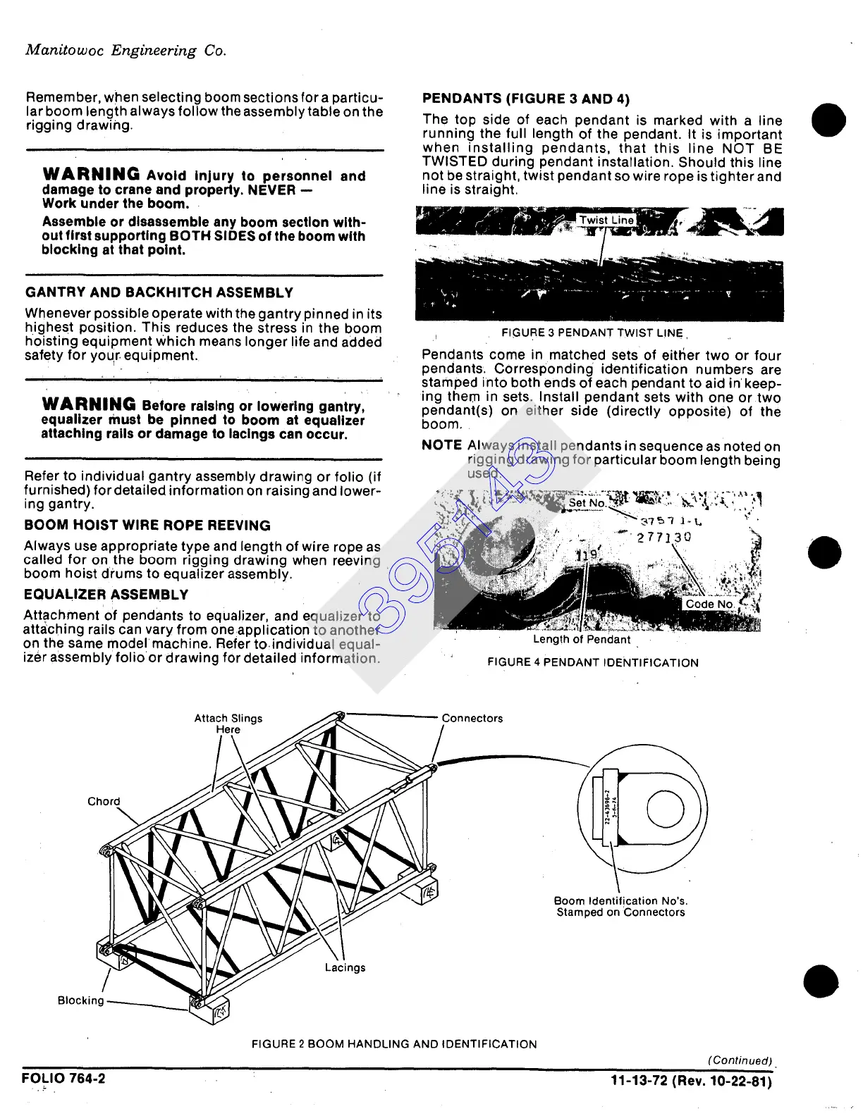
Attach Slings
Here
Connectors
Chord
4
Boom Identilication No's.
Stamped on Connectors
Blocking
Lacings
FIGURE 2 BOOM HANDLING AND IDENTIFICATION
(Continued)
FOLIO
764-2 11-13-72 (Rev. 10-22-81)
395143
 Loading...


