Manitowoc Engineering Co.
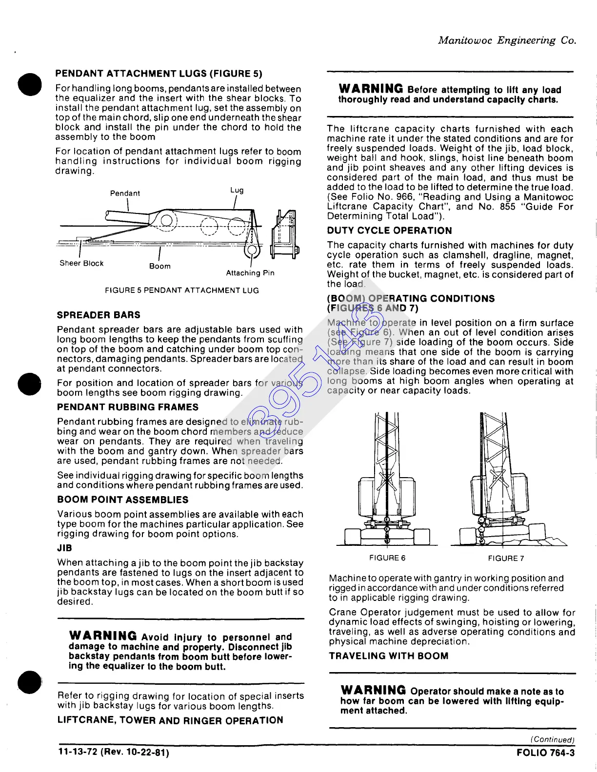
PENDANT ATTACHMENT LUGS (FIGURE 5)
For handling long booms, pendants are installed between
the equalizer and the insert with the shear blocks. To
install the pendant attachment lug, set the assembly on
top of the main chord, slip one end underneath the shear
block and install the pin under the chord to hold the
assembly to the boom
For location of pendant attachment lugs refer to boom
handling instructions for individual boom rigging
drawing.
Pendant Lug
, /,
Attaching Pin
FIGURE 5 PENDANT ATTACHMENT LUG
SPREADER BARS
Pendant spreader bars are adjustable bars used with
long boom lengths to keep the pendants from scuffing
on top of the boom and catching under boom top con-
nectors, damaging pendants. Spreader bars are located
at pendant connectors.
For position and location of spreader bars for various
boom lengths see boom rigging drawing.
PENDANT RUBBING FRAMES
Pendant rubbing frames are designed to eliminate rub-
bing and wear on the boom chord members and reduce
wear on pendants. They are required when traveling
with the boom and gantry down. When spreader bars
are used, pendant rubbing frames are not needed.
See individual rigging drawing for specific boom lengths
and conditions where pendant rubbing frames are used.
BOOM POINT ASSEMBLIES
Various boom point assemblies are available with each
type boom for the machines particular application. See
rigging drawing for boom point options.
JIB
When attaching a jib to the boom point the jib backstay
pendants are fastened to lugs on the insert adjacent to
the boom top, in most cases. When a short boom is used
jib backstay lugs can be located on the boom butt if so
desired.
WARNING
Avoid Injury to personnel and
damage to machine and property. Disconnect jib
backstay pendants from boom butt before lower-
ing the equalizer to the boom butt.
Refer to rigging drawing for location of special inserts
with jib backstay lugs for various boom lengths.
LIFTCRANE, TOWER AND RINGER OPERATION
WARNING
Before attempting to lift any load
thoroughly read and understand capacity charts.
The liftcrane capacity charts furnished with each
machine rate it under the stated conditions and are for
freely suspended loads. Weight of the jib, load block,
weight ball and hook, slings, hoist line beneath boom
and jib point sheaves and any other lifting devices is
considered part of the main load, and thus must be
added to the load to be lifted to determine the true load.
(See Folio No. 966, "Reading and Using a Manitowoc
Liftcrane Capacity Chart", and No. 855 "Guide For
Determining Total Load").
DUTY CYCLE OPERATION
The capacity charts furnished with machines for duty
cycle operation such as clamshell, dragtine, magnet,
etc. rate them in terms of freely suspended loads.
Weight of the bucket, magnet, etc. is considered part of
the load.
(BOOM) OPERATING CONDITIONS
(FIGURES 6 AND 7)
Machine to operate in level position on a firm surface
(see Figure 6). When an out of level condition arises
(See Figure 7) side loading of the boom occurs. Side
loading means that one side of the boom is carrying
more than its share of the load and can result in boom
collapse. Side loading becomes even more critical with
long booms at high boom angles when operating at
capacity or near capacity loads.
9
FIGURE 6
//
FIGURE 7
Machine to operate with gantry in working position and
rigged in accordance with and under conditions referred
to in applicable rigging drawing.
Crane Operator judgement must be used to allow for
dynamic load effects of swinging, hoisting or lowering,
traveling, as well as adverse operating conditions and
physical machine depreciation.
TRAVELING WITH BOOM
WARNING
Operator should make a note as to
how far boom can be lowered with lifting equip-
ment attached.
(Continued)
11-13-72 (Rev. 10-22-81) FOLIO 764-3
395143
 Loading...


