. ." ' . • .
MANITOWOC ENGINEERING
diuision of The
Man/towoc
Company, Inc.
EQUALIZER ASSEMBLY
3g00T
PURPOSE
This folio describes equalizer to pendant rigging, and
attaching of equalizer to equalizer attaching rails for
boom handling and gantry raising and lowering.
RIGGING EQUALIZER ASSEMBLY
(FIGURE 1)
For various crane operations install pendants in pen-
dant links at specific equalizer lugs, and directly into
equalizer lugs as described in Table below:
CRANE PENDANT
OPERATION LINKS LUGS BOOM NO'S
Liftcrane A 9
OTT 1 B A 9A
Liftcrane E 9
HHT 2 C,D* A 9A
Tower A 9
B A
9A
1. OTT -- Open Throat Top
2. HHT -- Hammerhead Top
* Link D used onlywith basic HHT Boom (33 ft.).
E D
A L~~~B D
...~
FIGURE 1
ATTACHING EQUALIZER TO RAILS
A. LIFTCRANE AND DUTY CYCLE OPERATION
(FIGURES 1 AND 2)
1. When the equalizer is lowered onto the boom butt it
normally lands with lug F at lower hole G of the equalizer
©Manitowoc 1982 '
CO.
.,Yla,-d, towoc, Wisconsin 54220
iiiii i i
I
attaching rails. The equalizer can now be pinned to
either hole G or upper hole H, [Use a lever hoist(come-
along) to pull equalizer to desired position.].
2. The equalizer is pinned with lug F of the equalizer at
hole H of the equalizer attaching rails to provide neces-
sary slack for assembling or disassembling the boom.
3. Additional pendant slack can b e gained by pulling the
equalizer onto the permanent or removable (however
equipped) equalizer rails, item I, onthe first insert.
4. For handling partial boom lengths the equalizer can
be pinned to either hole G or H with lug F of equalizer.
For cranes equipped with a No. 9A boomequalizer att-
aching link J must be used when attaching equalizer to
hole H.
J
I
/
FIGURE 2
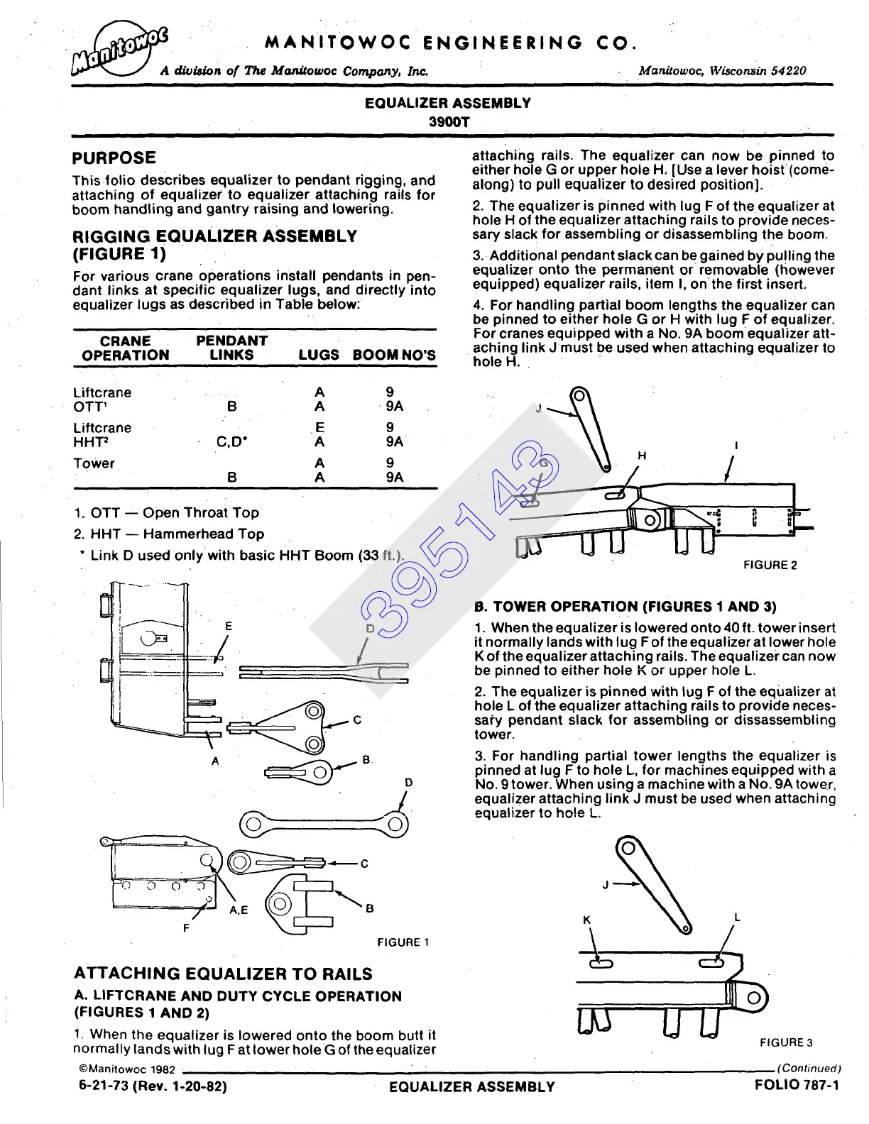
B. TOWER OPERATION (FIGURES 1 AND 3)
1. When the equalizer is lowered onto 40 ft. tower insert
it normally lands with lug F of the equalizer at lower hole
K of the equalizer attaching rails. The equalizer can now
be pinned to either hole K or upper hole L.
2. The equalizer is pinned with lug F of the equalizer at
hole L of the equalizer attaching rails to provide neces-
sa~'y pendant slack for assembling or dissassembling
tower.
3. For handling partial tower lengths the equalizer is
pinned at lug F to hole L, for machines equipped with a
No. 9 tower. When using a machine with a No. 9A tower,
equalizer attaching link J must be used when attaching
equalizer to hole L.
FIGURE 3
(Continued)
IJ
6-21-73 (Rev. 1-20-82) EQUALIZER ASSEMBLY FOLIO 787-1
395143
 Loading...


