Swing-away lattice
3.4 Description of the rigging work
3 - 42 3 112 441 en Lattice extension operating instructions
GMK 4100/4100-L/5095
11.01.2008
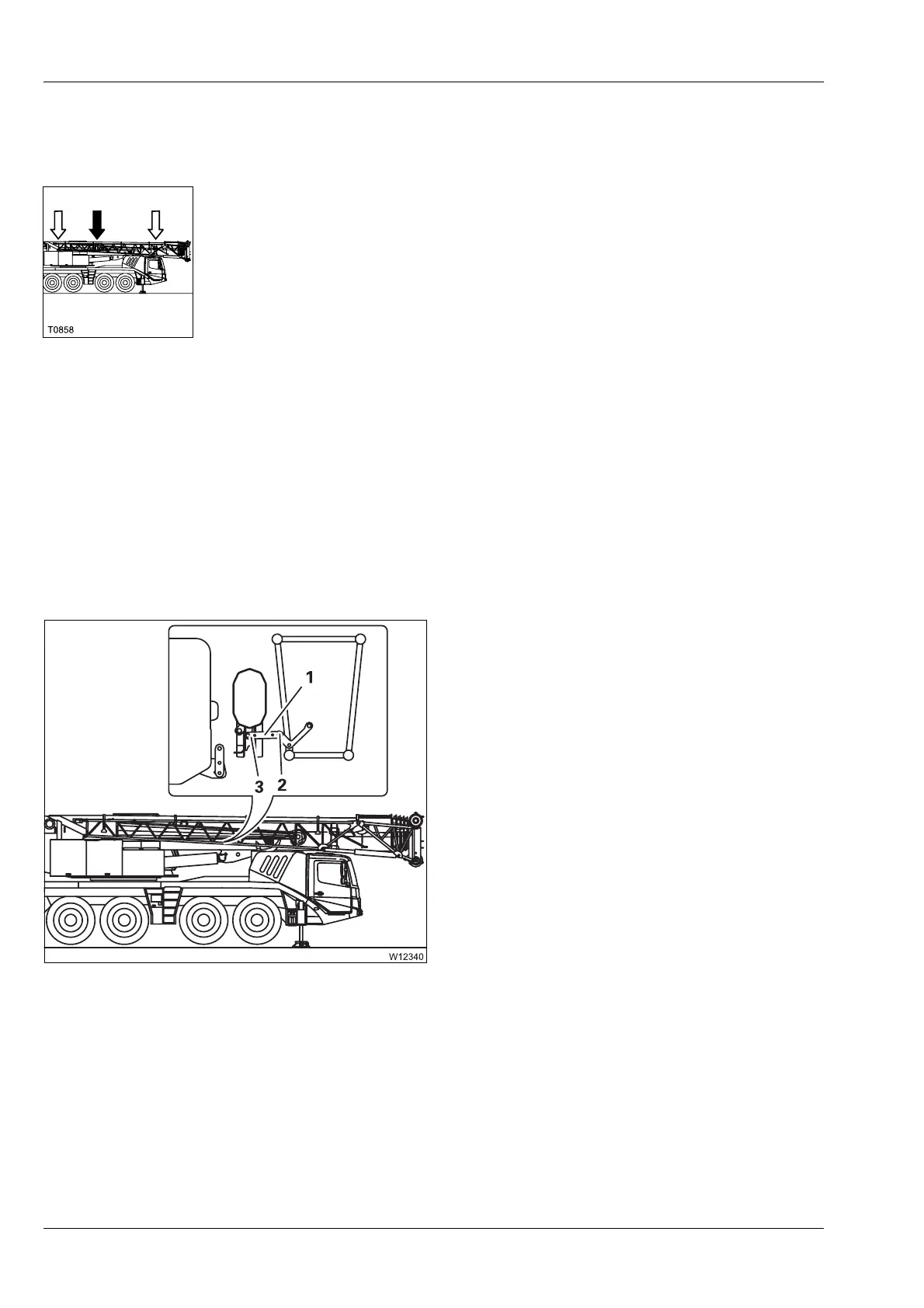
Connections in the
Middle area
The connections in the Middle area consist of a locking bar with two pins.
Depending on the position of the locking bar, different sections are con-
nected with one another. There are three positions:
– Position Section 1/section 2
– Position Section 2/main boom
– Position At section 1
Section 1 / section 2 position
This position must be established:
– When rigging the 17 m (56 ft) swing-away lattice – before the swing-away
lattice is swung in front of the main boom head
– When unrigging the 17 m (56 ft) swing-away lattice extension – after
swinging section 2 onto section 1
– When unrigging the 10 m (33 ft) swing-away lattice – if section 2 is
installed on the main boom
– When removing the 17 m (56 ft) swing-away lattice
• Pin the locking bar (1) to section 2 with the
pin (2).
• Pin the locking bar (1) to section 2 with the
pin (3).
• Secure the pins with the retaining pins.
 Loading...