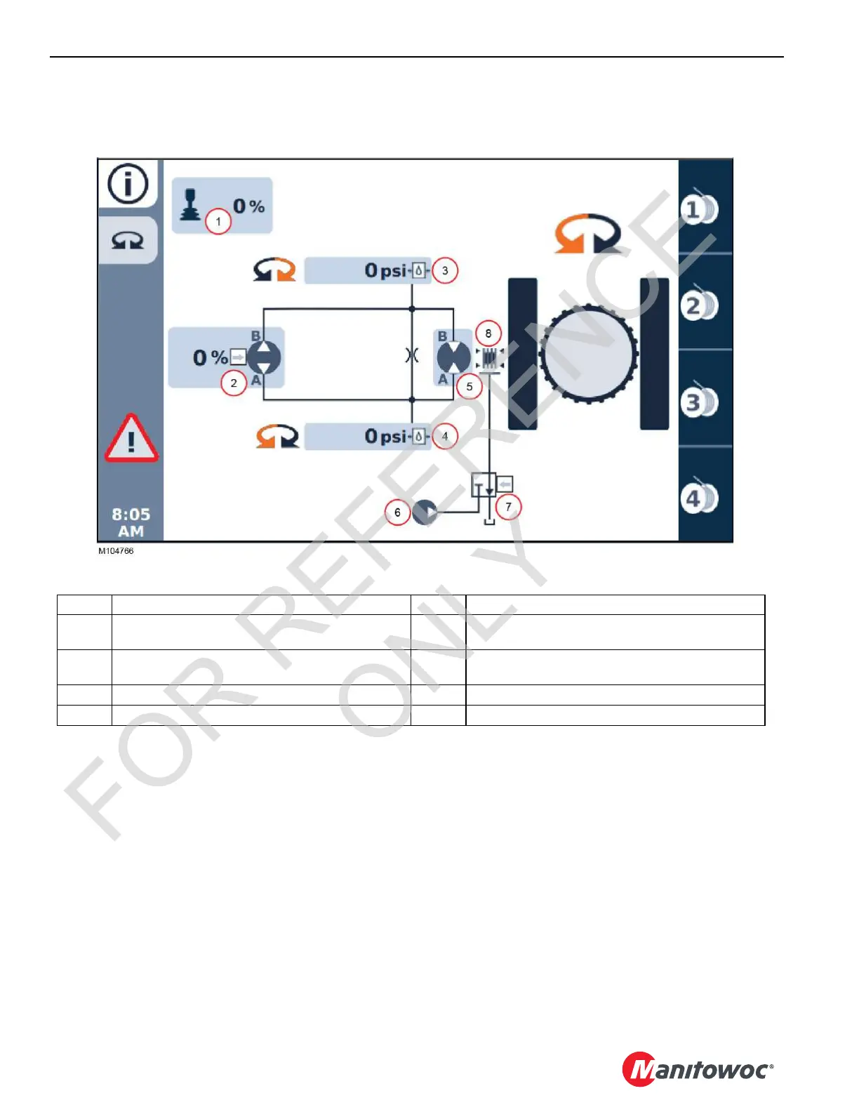
EasyManua.ls Logo

Manitowoc MLC100-1 - Swing Hydraulic Diagram

Manitowoc MLC100-1
188 pages
Print Icon
To Next Page IconTo Next Page
To Previous Page IconTo Previous Page
Loading...
SWING SYSTEM MLC80A-1/MLC90A-1/MLC100A-1/MLC100-1 SERVICE/MAINTENANCE MANUAL
6-4
Published 10-09-2020, Control # 259-06
Swing Hydraulic Diagram
A detailed hydraulic schematic is provided at the end of Section 2 in this Service Manual.
FIGURE 6-1
Item Swing Components Item Swing Components
1 Control Handle (Command -100 to 100%)
+ number = swing right, number = swing left
5Motor
2 Pump (Command -100 to 100%)
+ number = swing right, number = swing left
6 Accessory Pump
3 Pressure Sensor (Right Swing) 7 Brake Valve
4 Pressure Sensor (Right Left) 8 Brake
FOR REFERENCE
ONLY

Table of Contents

Other manuals for Manitowoc MLC100-1

Related product manuals