HOISTS MLC80A-1/MLC90A-1/MLC100A-1/MLC100-1 SERVICE/MAINTENANCE MANUAL
5-18
Published 10-09-2020, Control # 259-06
Free Fall System (Optional)
See Figure 5-10 and Figure 5-11.
Drum 1, Drum 2, or both drums can be equipped with the
free fall option. When FF is enabled, the large spring-
applied, hydraulically-released disc brake on the right end of
drum is used to control the lowering of a load. Raising a load
when free fall is enabled works the same as in normal
operation.
NOTE When the crane is not in free fall mode, depressing
the free fall brake pedal has no effect on hoist
operation.
The motor and the disc brake on the motor end of the drum
used on the free fall drum are the same as those used on the
non-free fall drum.
When equipped with free fall, the CCS determines whether
drum speed is taken from the motor speed sensor
(Figure 5-18 on page 5-25
) or from the free fall speed sensor
(Figure 5-19 on page 5-26
).
The speed sensor sends a signal to the rotation indicator
(thumper solenoid) in the control handle. The rotation
indicator pulsates with a varying frequency to indicate drum
rotational speed. The direction of rotation is also displayed
on the main display via an arrow on the corresponding drum
icon.
Cooling oil flow through the brake is continuous whether or
not the free fall mode is enabled. Cooling oil flow at 3.5 bar
(70 psi) is provided by the free fall cooling pump, which is
dedicated for this purpose.
Brake release pressure is provided by a the free fall pump
which is relief-valve limited to 66 bar (950 psi). The CCS
receives a position signal from the free fall brake pedal and
uses this information to proportionally adjust the brake
release pressure in order to allow the drum to free fall.
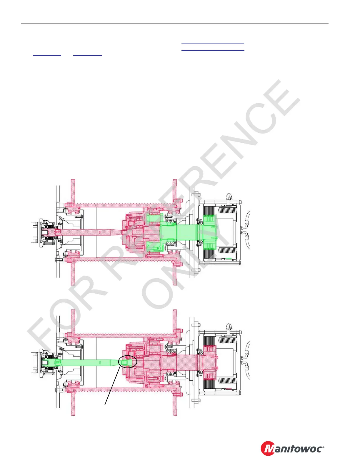
Drum Control Handle—Raise
Hoist Operates Normally
Drum Control Handle—Neutral
The load is controlled by the operator
using the clutch/brake pedal
Free fall brake is spring-engaged—
Brake shaft does not rotate, is
disconnected from drive gears.
Free fall brake can be
hydraulically released—
Brake shaft can rotate as the
clutch/brake is released. Brake
shaft is connected to drive gears.
Motor shaft disconnected from
drive gears
M100826
FIGURE 5-12
 Loading...


