ELECTRICAL SYSTEM MLC80A-1/MLC90A-1/MLC100A-1/MLC100-1 SERVICE/MAINTENANCE MANUAL
3-4
Published 10-09-2020, Control # 259-06
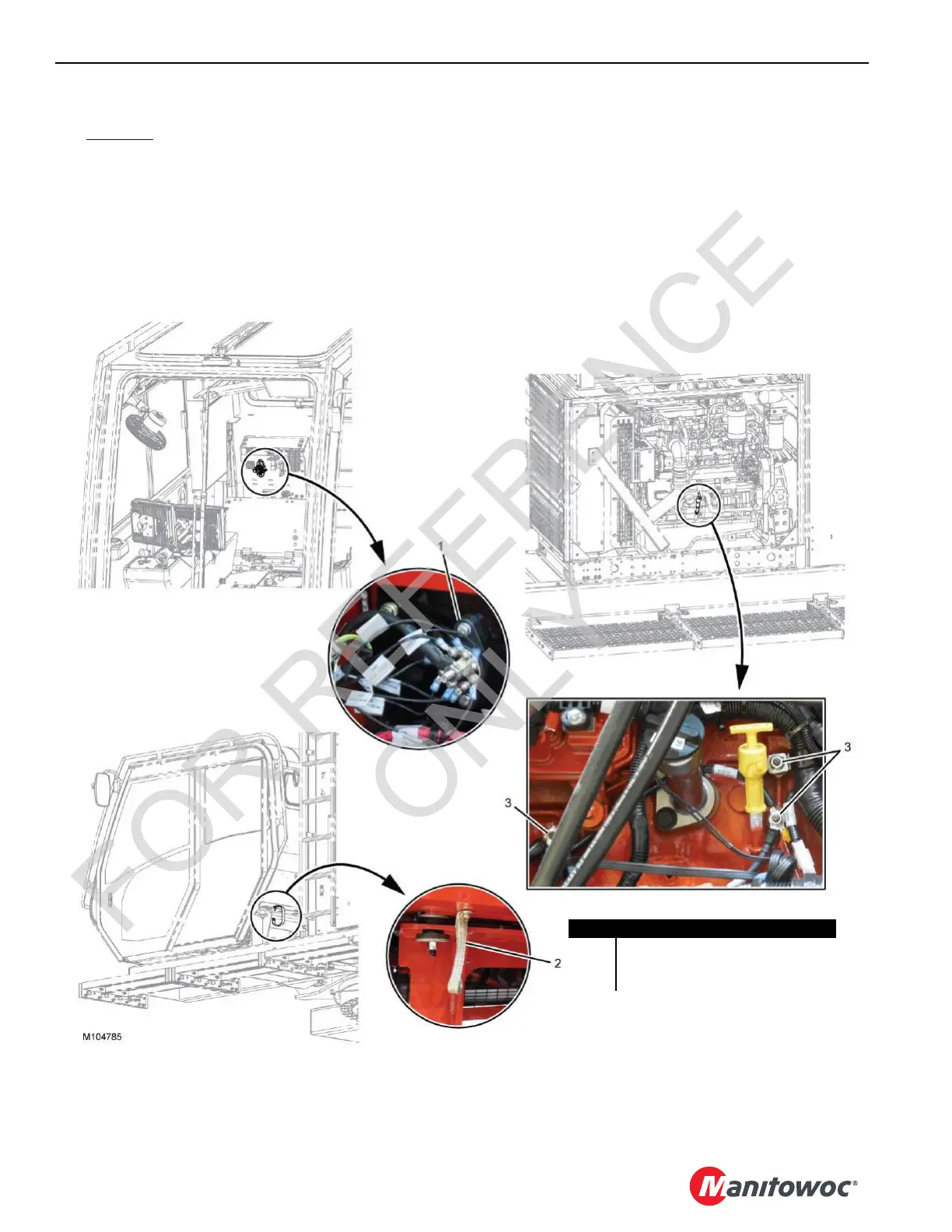
Rotating Bed and Cab Mount Ground Points
See Figure 3-2 for the following items.
The rotating bed ground points are as follows:
• Negative Remote Ground Terminal (1)—The negative
remote ground terminal is located on the battery
disconnect switch panel.
• Rotating Bed-to-Cab Arm Ground Strap (2)—Ensures
an electrical path to ground between the rotating bed
and the cab arm.
• Cab Arm-to-Cab Mount Ground Strap (3)—Ensures an
electrical path to ground between the cab arm and the
cab mount.
• Rotating Bed Main Ground Point—The rotating bed
main ground point is a ground stud located at the inside
right frame of the rotating bed. The ground stud provides
a single connection point for the ground circuit of all the
electrical devices located on the rotating bed and the
carbody. A ground cable connects the ground stud to the
negative battery terminal.
Item Description
1 Cab Ground Bus
2 Rotating Bed-to-Cab Ground Strap
3 Engine Ground
FIGURE 3-2
 Loading...


