Manitowoc Published 10-09-2020, Control # 259-06 2-17
MLC80A-1/MLC90A-1/MLC100A-1/MLC100-1 SERVICE/MAINTENANCE MANUAL HYDRAULIC SYSTEM
Servicing Suction Strainer
The suction line to the pumps is equipped with a suction
strainer located inside the hydraulic tank.
Service the suction strainer when the fault alarm
comes on and the Suction Pressure icon
appears in the Fault Bar of the main display.
To service the suction screen, the hydraulic tank must be
drained.
See Figure 2-14
for the following procedure.
1. Stop the engine and allow the hydraulic oil to cool.
2. Drain the hydraulic oil into a suitable container capable
of holding 302 L (80 gal).
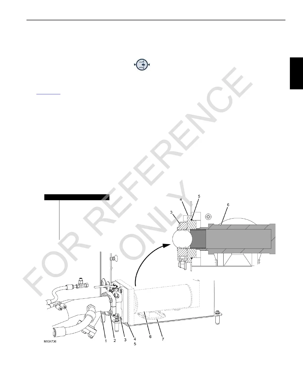
3. Disconnect the suction tube (1) and the split flange
assembly (2) from the shut-off valve (3).
4. Remove the screws attaching the valve mounting plate
(4) to the hydraulic tank.
5. Remove the shut-off valve (3), the valve mounting plate
(4), and the suction strainer (6) as an assembled unit
from the hydraulic tank.
6. Remove the suction strainer (6) from the valve mounting
plate (4).
7. Either replace the strainer with a new one or (if the
strainer is not damaged) clean it as follows:
a. Soak the suction strainer in a clean, nonflammable
solvent.
b. Brush off the outer surface.
c. Flush the strainer with solvent from the inside out.
8. Remove the access cover (7) and thoroughly clean the
inside of the hydraulic tank.
9. Fasten the suction strainer (6) to the valve mounting
plate (4).
10. Lubricate and install a new O-ring (5).
11. Fasten the shut-off valve (3), the valve mounting plate
(4), and the suction strainer (6) as an assembled unit to
the hydraulic tank.
12. Reconnect the suction tube (1) and split flange
assembly (2) to the shut-off valve (3). Lubricate and
install a new flange O-ring.
13. Reinstall the access cover (7).
14. Start the engine and check for leaks. Correct as needed.
Item Description
1 Suction Tube
2 Split Flange Assembly
3 Shut-Off Valve
4 Valve Mounting Plate
5O-Ring
6 Suction Strainer
7 Access Cover
FIGURE 2-14
 Loading...


