Manitowoc Published 10-09-2020, Control # 259-06 3-5
MLC80A-1/MLC90A-1/MLC100A-1/MLC100-1 SERVICE/MAINTENANCE MANUAL ELECTRICAL SYSTEM
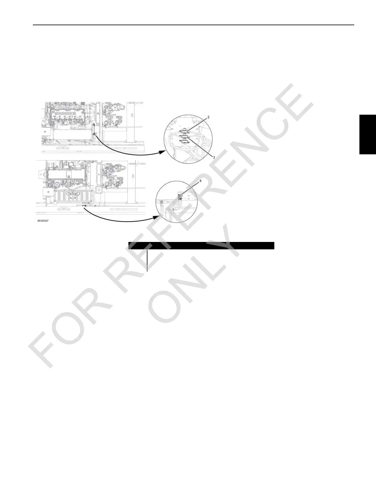
CIRCUIT BREAKERS, FUSES, AND RELAYS
Most circuit breakers, fuses, and relays are located in the
cab.
The following fuses and circuit breaker are not located in
fuse box:
• TCU CraneStar® (if equipped) 5A fuse F5 is mounted on
the battery disconnect switch bracket.
• Alternator 250A fuse F0 (2) is mounted on a panel at the
front of the battery box.
• Intake air heater 150A fuse F6 (3) is mounted on a panel
at the front of the battery box.
Item Description
1
CraneStar® 5A Fuse (F5)
2 Alternator 250A Fuse (F0)
3
I
ntake Air Heater 150A Fuse (F6)
FIGURE 3-3
Engine
Compartment
 Loading...


