ACCESSORIES MLC80A-1/MLC90A-1/MLC100A-1/MLC100-1 SERVICE/MAINTENANCE MANUAL
10-4
Published 10-09-2020, Control # 259-06
ACCESSORY SYSTEMS HYDRAULIC DIAGRAM
A detailed hydraulic schematic is provided at the end of Section 2 in this Service Manual.
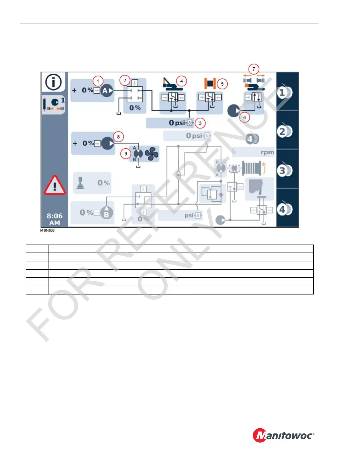
FIGURE 10-1
Item Accessory Systems Components Item Accessory Systems Components
1 Pump A (Command (0 to 100%) 6 Accessory System Pump (low pressure)
2 Accessory System Enable Valve (Command 0 to 100%) 7 Counterweight Pins Control Valve
3 Accessory System Pressure Sensor 8 Hydraulic Cooler Fan Pump (Command (0 or 100%)
4 Gantry Cylinders Control Valve 9 Hydraulic Cooler Fan Motor
5 Crawler Cylinder Control Valve
 Loading...


