National Crane Published 5-27-2018 Control # 039-06 7-1
800D SIDE SHIMMING OF BOOM SECTIONS
SECTION 7
SIDE SHIMMING OF BOOM SECTIONS
SECTION CONTENTS
Top/rear Side Pad Adjustment . . . . . . . . . . . . . . . 7-2
Inner Boom Pad Lubrication . . . . . . . . . . . . . . . . . 7-3
Jib Installation And Adjustment . . . . . . . . . . . . . . 7-4
Jib Jack Service & Maintenance . . . . . . . . . . . . . . 7-5
Adding Oil . . . . . . . . . . . . . . . . . . . . . . . . . . . . . . . 7-6
Changing Oil . . . . . . . . . . . . . . . . . . . . . . . . . . . . . 7-6
Lubrication . . . . . . . . . . . . . . . . . . . . . . . . . . . . . . 7-6
Rust Prevention . . . . . . . . . . . . . . . . . . . . . . . . . . 7-6
Troubleshooting . . . . . . . . . . . . . . . . . . . . . . . . . . . 7-6
(Optional) Oil Cooler Service & Maintenance . . . 7-6
Swing Drive Service . . . . . . . . . . . . . . . . . . . . . . . . 7-8
Lubrication and Maintenance . . . . . . . . . . . . . . . . 7-8
Disassembly Procedure . . . . . . . . . . . . . . . . . . . . 7-8
Assembly Procedure. . . . . . . . . . . . . . . . . . . . . . . 7-9
Rotation Stop-mechanical . . . . . . . . . . . . . . . . . . 7-10
Adjustment Procedure . . . . . . . . . . . . . . . . . . . . . 7-10
Servicing The Control Valves. . . . . . . . . . . . . . . . 7-11
Disassembly and Reassembly of Control
Valves to Replace Seals . . . . . . . . . . . . . . . . . . . 7-11
Replacing Spool Seals. . . . . . . . . . . . . . . . . . . . . 7-11
Unloader Valve Service. . . . . . . . . . . . . . . . . . . . . 7-12
Control Valve Relief Adjustment . . . . . . . . . . . . . 7-13
Mid-inlet Relief Adjustment . . . . . . . . . . . . . . . . . 7-13
Unloader Dump Valve – Air Purging
Instruction . . . . . . . . . . . . . . . . . . . . . . . . . . . . . . . 7-14
Hydraulic System Description . . . . . . . . . . . . . . . 7-14
Optional Hydraulic Capacity Alert System . . . . . 7-15
System Adjustment . . . . . . . . . . . . . . . . . . . . . . . 7-15
Troubleshooting . . . . . . . . . . . . . . . . . . . . . . . . . . 7-16
Maintenance & Repair . . . . . . . . . . . . . . . . . . . . . . 7-18
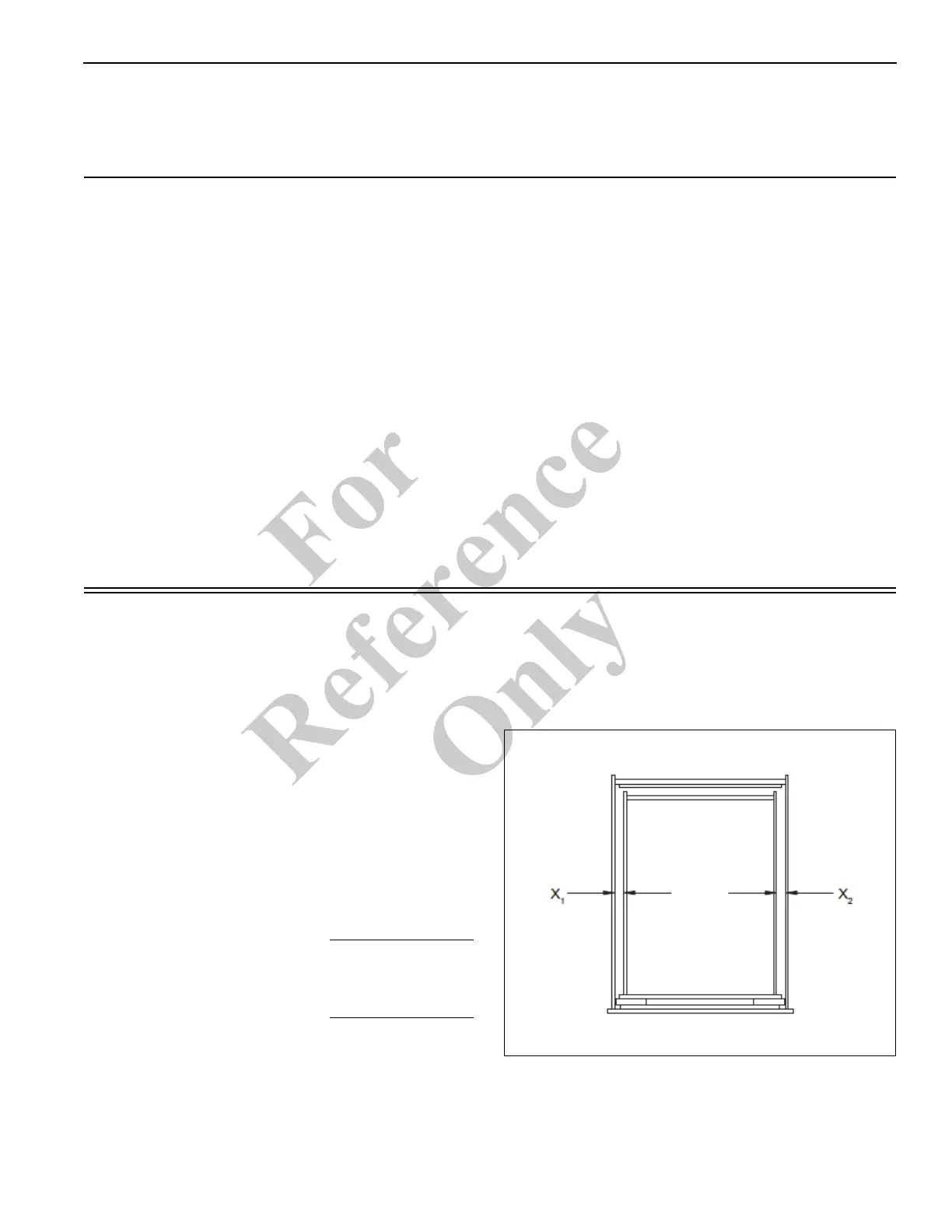
Center inner boom section in outer boom section.
X
1
= X
2
Calculate shims required.
Gaps X
1
= X
2
= 0.56 in (14.3 mm).
Wear pad thickness (t
wp
) = 0.44 in (11.1 mm).
Add shims as required [each shim is 0.03 in (0.8 mm)] to
tighten the pads so that there is 0.03 in - 0.09 in (0.8 mm -
2.4 mm) total clearance between the sections. In some
cases it will be necessary to have an unequal number of
shims behind the pads at the top and bottom side pad
locations.
At each pad location add qty-1 0.06 in (1.6 mm) and qty-
1.03 in (0.8 mm) shim for a total clearance of 0.03 in
(0.76 mm).
X1 = 0.56in (14.3mm)
- t
wp
=
0.44 in (11.1 mm)
clearance before shims 0.12 in (3.2 mm)
Add shims 0.03 in (0.8 mm)
0.06 in (1.6 mm)
Final clearance 0.03 in (0.8 mm)
Fo
r
Reference
Only

 Loading...


