SIDE SHIMMING OF BOOM SECTIONS 800D
7-16
Published 5-27-2018 Control # 039-06
before the chosen radius is reached or allows extension
beyond the chosen radius, adjustment is required. If the
system is activated before trip pressure is reached,
lower the load, remove acorn nut and loosen the locking
nut on the compensating pressure switch and turn the
setscrew clockwise to increase trip pressure.
5. When the gauge reaches trip pressure, turn the
setscrew counter-clockwise until the system solenoid is
deactivated and tighten the locking nut. Retract the
boom until the pilot pressure is reduced enough to
reactivate the system solenoid. The hydraulic capacity
alert indicator light will go out when the solenoid is
reactivated. Check the trip pressure setting by extending
the load until the chosen radius is reached. As the
chosen radius is reached, the system solenoid should
be deactivated and the indicator light should come on.
Readjust switch head if trip pressure is not correct.
6. Once proper adjustment is verified, return the boom to a
firmly supported position, stop the truck engine and
replace covers.
TROUBLESHOOTING
The following step-by-step analysis will be helpful in isolating
and correcting almost every service problem if followed in a
step-by-step systematic manner. Use this information with
the Hydraulic Schematic and the Illustrated Parts Catalog to
identify parts and follow flow paths. Start at top box and work
downward step by step - don’t try to start in the middle or skip
steps.
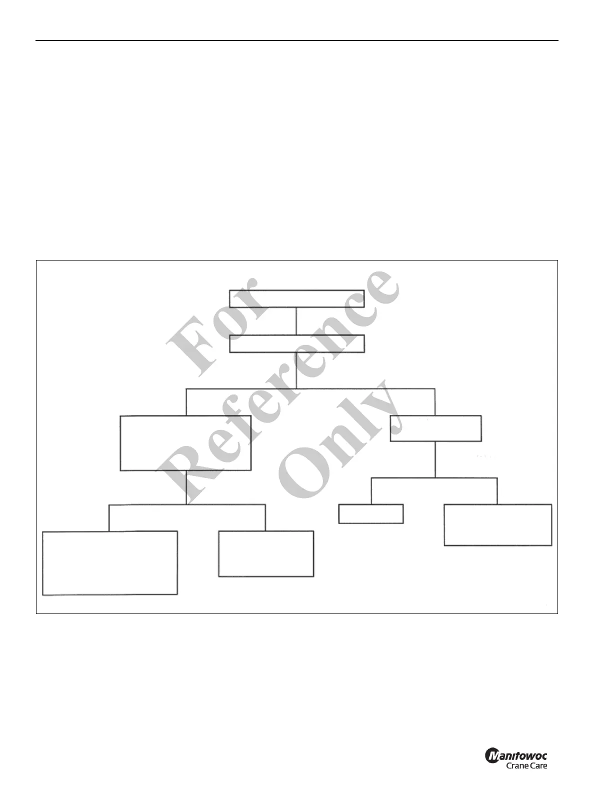
Boom Creeping Down
Control Valve Centered
YES NO
Cap Sensing Line Between
Counterbalance Valve and
Compensating Pressure
Switch
Control Valve in
Meter in Position
Control Valve in
Down Position
Normal Operation
Center Valve
YES NO
Replace
Compensating
Pressure Switch
Incorrect Counterbalance
Setting
Bad Counterbalance Valve
Leaking Cylinder Seals
Still Creeps Stops Creep
9423
Fo
r
Reference
Only
 Loading...


