National Crane Published 5-27-2018 Control # 039-06 2-11
800D OPERATION
2. When Lifting Over the Front of the Truck and the Vehicle
is Equipped with a Front Stabilizer
A front stabilizer is required when loads are to be lifted
over the front of the vehicle. Before conducting any
boom operations, extend both outriggers until the
chassis weight is removed from the wheels. Level the
crane side-to-side using the level indicator located at
either control station as a reference. Then extend and
lower the rear stabilizers to level the crane front-to-
back. Again refer to the level indicator to insure that the
crane is properly leveled. After the crane is leveled side-
to-side and front-to-back, extend the front stabilizer
leg(s) until firm contact is made with the ground. Always
keep the load as close to the ground as possible.
3. Rear Mount Units Equipped with Rear Stabilizer A rear
stabilizer is required when loads are to be lifted over the
rear of the vehicle. Before conducting any boom
operations, extend both outriggers until the chassis
weight is removed from the wheels. Level the crane
side-to-side using the level indicator located at either
control station as a reference. Then extend and lower
the HO outriggers to level the crane front-to-back. Again
refer to the level indicator to insure that the crane is
properly leveled. After the crane is leveled side-to-side
and front-to-back, extend the rear stabilizer leg until firm
contact is made with the ground. Always keep the load
as close to the ground as possible.
Do not operate outrigger beams or legs unless they are
visible to either the operator or a designated signal
person to avoid crushing injury.
4. Check to ensure that the jib, if so equipped, is stowed
correctly on the first section boom.
BEFORE MAKING THE LIFT
1. Check all controls for proper operation by operating
each system through one complete cycle. This is
particularly important after the unit has been serviced or
repaired. If any abnormal operations are detected,
correct the condition before continuing.
2. During all operations, the controls should be metered
when beginning or terminating a movement to prevent
sudden starting or stopping which imposes undue shock
loads on the equipment. This metering can be
performed by metering the control lever and the foot
throttle.
3. Check the operating area for electric powerlines.
READING AND UNDERSTANDING THE
LOAD CHARTS
The structures and components of your unit are designed to
provide satisfactory service if the unit is not loaded in excess
of the maximum rated loads specified on the load chart.
Overloading can create serious potential safety hazards and
can also shorten the service life of your unit. It is important
that you know the weight and radius of any load that you are
attempting to handle. This should be done by use of a
dynamometer and tape measure or by contacting your
supervisor.
Overloading a crane can
cause many types of failure
depending on the
configuration and working
position of the crane, i.e.
structural damage to almost
any part of the crane hoist or
cable failure and tipping the
unit over.
The load chart shows the maximum rated loads including
load (weight being lifted), load handling equipment such as
slings, buckets, and downhaul weights, etc. which can be
handled by the crane and the hoist. The weight of the load
handling equipment and boom attachments must be
deducted from the maximum load rating shown on the load
chart to determine the payload which can be lifted. Additional
reduction may be necessary to make allowance for such
factors as the effects of freely swinging loads, wind, ground
conditions, out-of-level conditions and operating speeds.
The ratings shown on the outrigger full span load chart are
maximum loads and are based on the structural integrity of
the crane in shaded areas, the stability of the crane in
nonshaded areas. The stability or non shaded areas
represent a stability tipping factor of 85% when:
1. All outriggers are extended with positive contact on firm,
level surface, the tires are free of the ground and the
machine is level within 1°.
2. The proper amount of counterweight has been installed,
if required.
3. The unit is mounted in accordance with factory
instructions on a vehicle with proper specifications.
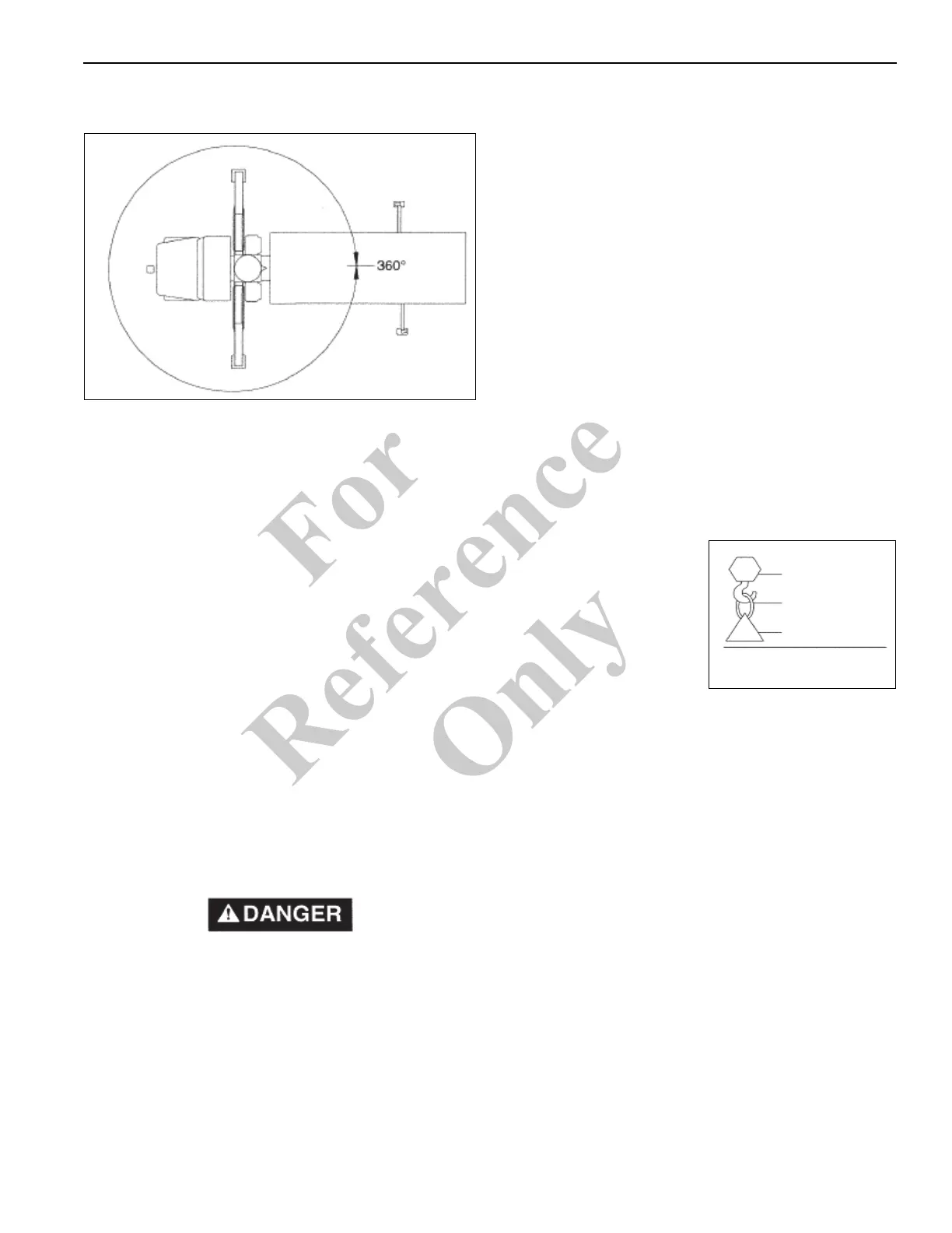
BLOCK
SLINGS
+
LOAD
+
TOTAL RATED LOADS
9348
Fo
r
Reference
Only

 Loading...


