SIDE SHIMMING OF BOOM SECTIONS 800D
7-14
Published 5-27-2018 Control # 039-06
1. Disconnect the hose from one of the outrigger sections
and plug the port. This function can be used to test the
system pressure without the hoses or cylinder seeing
the higher pressure.
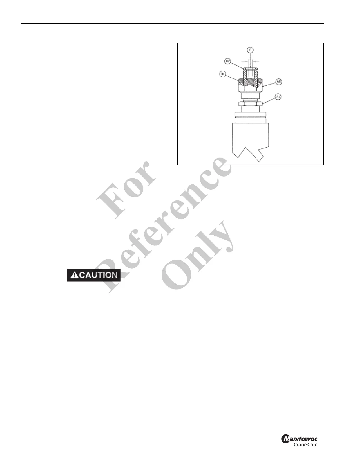
2. Remove the fitting from the relief valve at C.
3. Insert a plug with a diameter of 0.31 in (7.9 mm) and a
length of 0.31 in (7.9 mm) in the cavity at C.
4. Screw a SAE -4 fitting into the port at C until it is tight.
5. Loosen jam nut B1 and with a wrench on the two wrench
flats at B2 either screw the threaded body in or out.
Screwing the body in increases the pressure setting.
Screwing the body out reduces the pressure setting. The
pressure can be read on the gauge on the console
during adjustment. Correct pressure is listed above.
6. Once the correct pressure is attained, tighten jam nut B1
while holding the body with the wrench at B2.
7. Recheck the pressure on the console gauge to ensure
that tightening the jam nut has not changed the pressure
setting. Never set pressure above recommendations.
8. Remove the SAE -4 fitting and plug from location C.
9. Reattach the hydraulic line at C and check for leaks.
10. Reconnect hose to outrigger function.
Some valve sections include work port reliefs. The work port
reliefs are shim adjustable. Adjustment is made by adding or
taking out shims. Adding a 0.010 shim will increase pressure
100 psi (0.68 MPa). See “Specifications” section for correct
pressure settings. Never set pressure above
recommendations.
If the machine does not perform properly at these
pressures, the problem is not the relief valve and no
attempt should be made to readjust the setting. If the
relief valves are set to higher pressures than those
listed above, the warranty on the machine is void. Also
the machine could operate in a manner such as to
endanger personnel safety.
UNLOADER DUMP VALVE – AIR PURGING
INSTRUCTION
When a crane sits for a long period, the oil can drain back to
the reservoir and air could get into the pilot lines of the
unloader dump valves. This is likely to be more of a problem
in colder weather as the oil will not flow back into the
unloaders as easily when the crane is started. If the unloader
pilot tubes have air in them, the dump functions will not work
correctly. They might appear to be dumping the flow even
though the ATB or overload switch has not been tripped. If
this is suspected when checking the systems during start-up,
first try to purge any air that may be in the system.
Purposely trip the ATB switch to open the dump solenoid.
Engage each function that is being dumped (telescope out,
hoist up, and boom down) separately at full throttle for about
a minute, longer if the oil is cold. Then engage all three
simultaneously. Remove the two-block condition and check
performance of each function. If there is no change, the
procedure may be repeated. If again there is no
improvement, follow the troubleshooting steps outlined for
checking and inspecting the ATB solenoid and work port
unloaders.
HYDRAULIC SYSTEM DESCRIPTION
The hydraulic system of this machine is an open center type
consisting of a fixed displacement three section high
pressure pump which supplies oil to a main control valve and
a hoist control valve. The main control valve is equipped with
a main inlet and a mid inlet. The main inlet supplies oil to the
turn function, the mid inlet supplies the remainder of the
crane function requirements. The main control valves
contain inlet section reliefs or port reliefs which limit pressure
in the hydraulic system to acceptable levels and control
Fo
r
Reference
Only

 Loading...


