OPERATION 800D
2-22
Published 5-27-2018 Control # 039-06
7. With power on and stabilizer beam fully extended,
ensure LED (6, Figure 2-9) on proximity switch
illuminates. Retract stabilizer beam and ensure LED is
not illuminated.
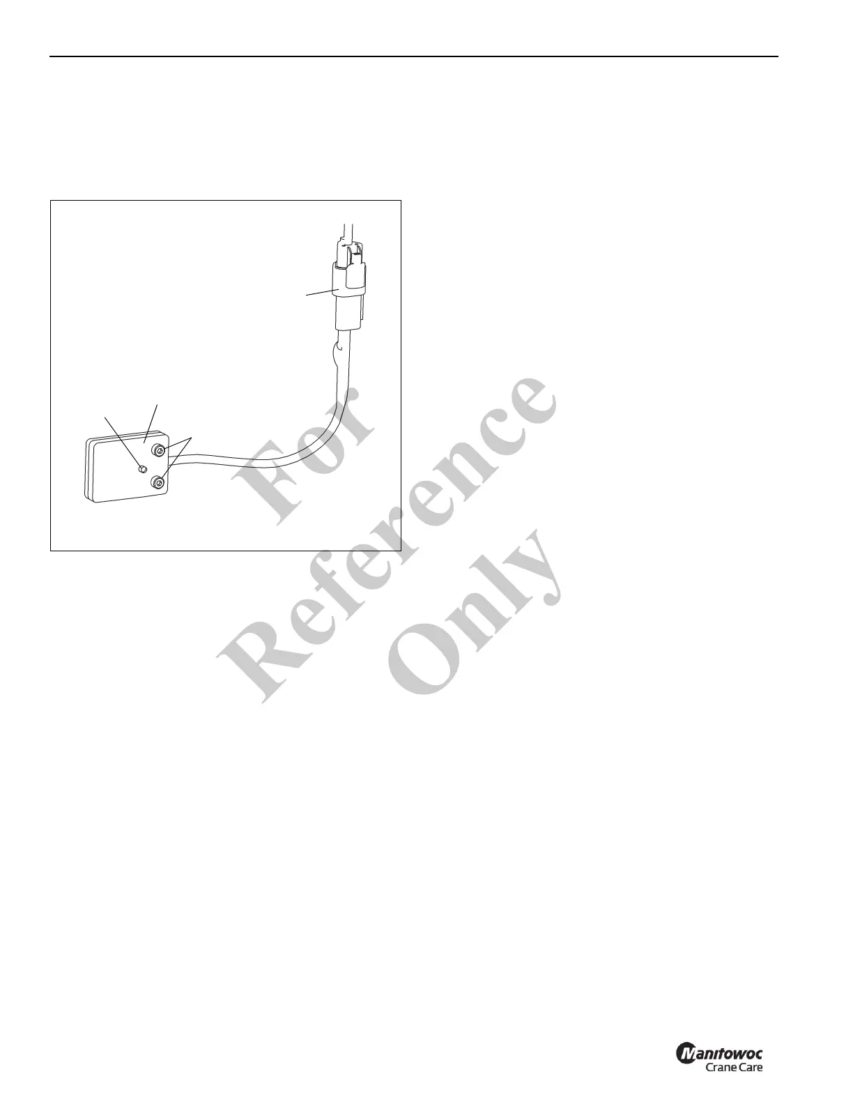
Stabilizer Proximity Switch (version 2)
Remove
1. Disconnect electrical connector (1, Figure 2-10) at
switch.
2. Remove the two screws (2, Figure 2-10) securing the
switch (4) to the stabilizer box. Remove switch.
Install
1. Fully extend stabilizer beam (horizontally).
2. Using two screws (2, Figure 2-10) secure the switch (4)
to stabilizer box.
3. Connect electrical connector (1, Figure 2-10) to switch.
4. With power on and stabilizer beam fully extended,
ensure LED (3, Figure 2-10) on proximity switch
illuminates. Retract stabilizer beam and ensure LED is
not illuminated.
ANTI-TWO BLOCK SYSTEM
Description/Operation
With untrained or inexperienced or distracted operators, two
blocking the hoist cable is a very real possibility. When the
hoist cable and end attachments contact the underside of the
sheave case, whether by hoisting up or extending the boom
without paying out the hoist cable, the hoist cable can be
damaged by crimping or over tensioning.
The anti-two-block system provided on your National Crane
can help prevent cable damage by sensing the position of
the hoist cable end attachments with respect to the sheave
case and disabling the functions that can cause a two block
condition.
The anti-two-block system consists of normally open, work
port unloader valves in the main and hoist control valves.
When the cartridge solenoid is energized, the crane
functions normally, when de-energized, the oil to the boom
extend, boom down, and hoist up crane functions are
diverted to tank. These solenoids are controlled by a limit
switch, which is attached to the boom or jib sheave case.
This switch is held in the closed position by a chain
suspended weight. The weight, which is looped around the
hoist cable, causes the contacts to remain closed until the
hoist cable end attachments contact the weight and release
the tension on the switch. At this point the contacts in the
switch open, breaking electrical continuity through the circuit
provided by the internal anti-two-block cord routed with a reel
or through the boom. When this continuity is broken, the
unloader cartridges de-energize and divert the function oil to
tank.
An audible and visual warning of the two block condition is
provided by the display console of the RCL system. See RCL
operators handbook for additional information.
If the machine is equipped with an optional Hydraulic
Capacity Alert (HCA) system, an indicator light provided on
the console will alert the operator when a two block condition
is detected.
Normal functioning is restored by hoisting down (or retracting
boom) until the weight is once again suspended freely.
Occasionally if the hoist up and boom extend functions are
operated at maximum speed in the dump mode, the back
pressure induced in the circuit will cause the hoist up or
boom extend functions to creep slightly (with no load on the
hook). Such a condition is not cause for alarm, as the back
pressure is not of sufficient magnitude to damage the cable
or end connections.
Fo
r
Reference
Only

 Loading...


