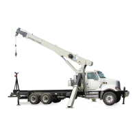
CRANE INSTALLATION 800D
10-12
Published 5-27-2018 Control # 039-06
inclinometer (measures to within 0.1°, Example:
SMARTTOOL DIGITAL LEVEL) adjust boom angle to 0°
(range -0.5° - +0.5°) and mechanically adjust the angle
sensor so that the system reads the angle to ±0.0 deg. of
the measured angle. Press “OK” when the sensor is
mechanically set, this confirms the mechanical
adjustment.
The display should now read BOOM TO 40.0 DEG, XX.X
DEG, EXIT. Raise boom to approx. 40° (range 35° to
45°). When the boom angle is within the calibration
range, the screen will add “CHANGE” & “OK” text.
Measure the boom angle with the inclinometer.
Compare this with the displayed angle and select
“CHANGE” and press “OK”. Use the “UP” & “DOWN”
arrow buttons to adjust the displayed angle to match the
measured angle. Once the display shows the correct
angle press “OK”.
The display will now define a mid correction angle, 65
DEG. Raise boom to approx. 65° and repeat above
steps.
The display will then define a high correction angle, 75
DEG. Raise boom to approx. 75° and repeat above
steps.
After pressing “OK” the system will request the angle
sensor calibration be saved. Select “YES” then press
“OK” to confirm calibration.
Press “EXIT” to leave calibration or select “CALIBRATE
SENSORS” to calibrate another sensor.
12. After selecting “CALIBRATE SENSORS” select “LEN” to
begin length sensor calibration. Screen will read FULLY
RETRACT MAIN BOOM XX.X ft., OK & EXIT. Refer to
load chart and elevate the boom to an angle that allows
boom to be fully extended. Verify the retracted boom
length is correct and press “OK”. The screen will now
read FULLY EXTENDED MAINBOOM XX.X ft. OK &
EXIT. Fully extend the main boom and press “OK”.
NOTE: The RCL system measures boom length from
the pivot pin to the center of the boom tip sheave. This
varies slightly from length indicated on Load Chart (see
table below).
After pressing “OK”, the system will request the length
sensor calibration be saved. Selected “YES” then press
“OK” to confirm calibration.
Press “EXIT” to leave calibration.
Verify length and angle indication are accurate and
replace cable reel cover.
13. Load indicating accuracy is verified by lifting known
loads. Select one or more known test loads that will load
the crane to full capacity, preferably a load that can fully
load the crane at more than one rated boom length. The
test loads including blocks, slings, etc. are to be known
accurate within ±1%.
Starting with a rated boom length and a short radius
(high boom angle), lift a load that is somewhat lower
than rated capacity at this condition. Increase the radius
slowly by decreasing the boom angle until the limit signal
is activated. Measure and record radius along with the
test load. Complete this for each test condition. If you
have selected a test load that is within the crane’s
capacity at the next longer rated boom length (closer
load radius at higher boom angle), you can reposition
the same test load for an additional test condition. A
minimum of four tests with one or more at full boom
extension are recommended.
For each test condition, refer to the Load Capacity Chart
and determine the rated load for the measured radius
condition. If the measured radius is between those listed
on the Capacity Chart, the rated load (for this test work
only) shall be determined by linear interpolation.
The load indicating accuracy is determined by this
formula:
TEST LOAD/RATED LOAD x 100 = % of Rated Load
The actual test load which activates the limit signal is not
to be less than 90% of the rated load nor more than
100% of the rated load for the corresponding actual load
radius.
MODEL
CAP. CHART
RETRACT
CAP. CHART
EXTEND
RCL
RETRACT
RCL
EXTEND
869D
880D
890D
8100D
27 ft
24.5 ft
27 ft
29 ft
69 ft
80 ft
90 ft
100 ft
26.6 ft
24.1 ft
26.6 ft
29.1 ft
68.6 ft
79.6 ft
89.6 ft
99.6 ft
The RCL system measures boom length from the pivot pin to the center of the
boom tip sheave. This varies slightly from length indicated on Load Chart.
Fo
r
Reference
Only

 Loading...


