20
D00619EN - v0 SWING OPERATOR - INSTALLATION MANUAL
5.5
F
WARNING: Attach the door’s leaf-joining point to the arm correctly, using reinforcements where necessary.
• Turn the nut (Fig. 8 part A) to preload the spring, until the plate ends (Fig. 8 part. B) coincide with the line indicating the
start point of the EN4 range (level L=0).
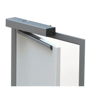
• Place the arm connection (Fig. 9 part A) on the operator output axis, so that the first part of the arm is perpendicular to
the operator mounting surface (Fig. 17).
• Tighten the screw (Fig. 9 part C) so that the arm connection remains anchored to the operator output axis.
• Screw in the three M8 x 16 hexagon button-head screws (Fig. 16 part B) without tightening so that the parts that make
up the articulated arm are joined together.
• With the leaf close, turn the part of the arm where the connection is to slightly compress the spring (see fig. 17).
• Fix the adjustment by firmly tightening the three M8 x 16 fixing screws (Fig. 16 part. B).
• Adjust the spring [see section ‘Spring Adjustment’].
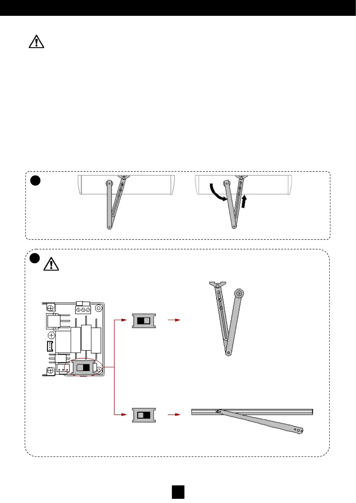
WARNING: After installing the rigid arm and the guide, ALWAYS check that the Switch position is to the
left, as in Fig. 11.
Fig. 17.
Fig. 11.
5.5
E