26
D00619EN - v0 SWING OPERATOR - INSTALLATION MANUAL
CARACTERÍSTICAS MECÁNICAS
5.15 Installing and Acquiring the Sensors
The operator is prepared to manage:
• Safety sensors (see Fig. 21 A and B): they are mounted on the leaf and control the nearby area to detect possible
obstacles, and stop movement or invert it to prevent blows, crushing or other sources of danger;
• Detection sensors (see Fig. 21 C and D): normally mounted on the wall, to detect when persons approach the door and
control the opening.
Connect the following sensors if they are present:
If, when the device is put into operation, the configuration of the supervised safety sensors has not yet been memorised, the
display will show error E6. Exit this state by activating the automatic supervised sensor acquisition procedure (parameter LS,
see section ‘Managing Operating Parameters of the Display’). During this procedure, the card waits until the sensors are
deactivated and checks the their supervision has been activated.
ID SENSOR DIAGRAM
17 = 0
30 = 1
Safety sensor supervised during closing (See Fig. 21 A) See Fig. 23
17 = 0
30 = 1
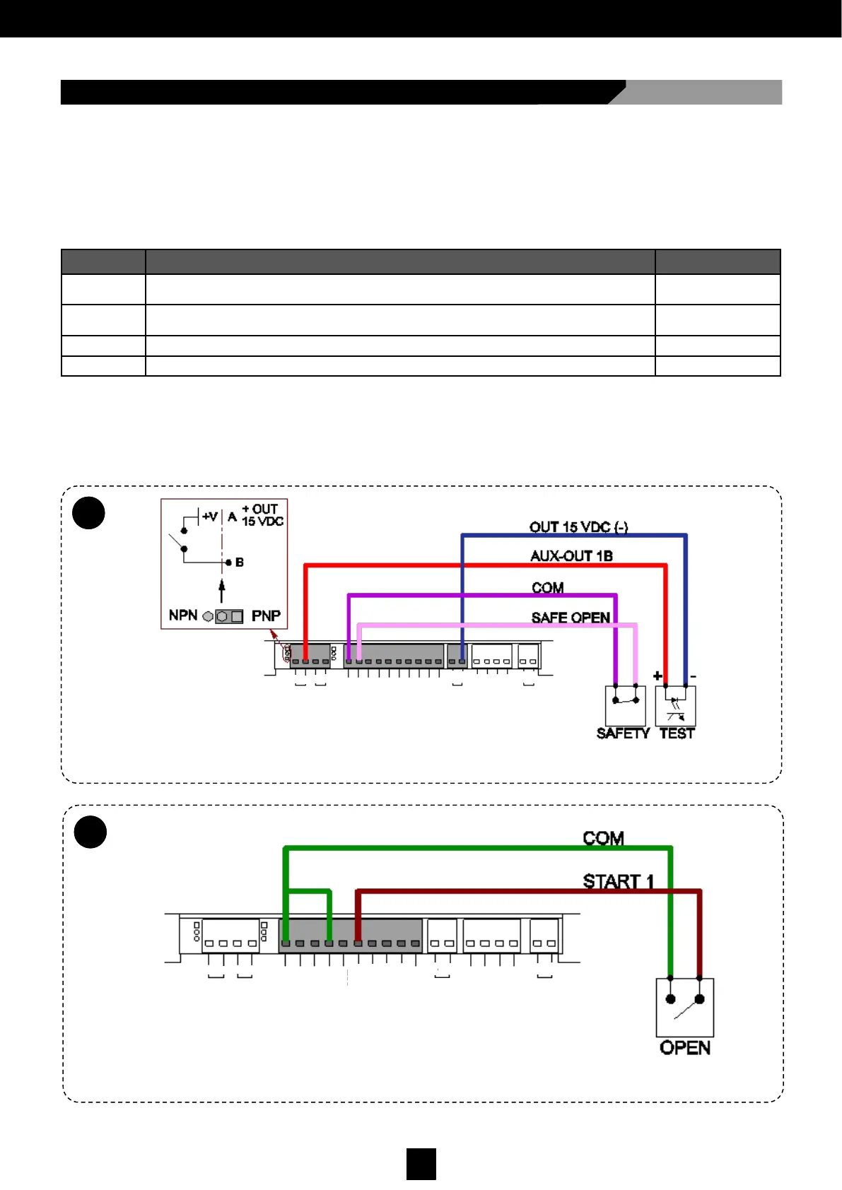
Safety sensor supervised during opening (See Fig. 21 B) See Fig. 24
Detection sensor (radar) on entry (See Fig. 21 D) See Fig. 25
Detection sensor (radar) on exit (See Fig. 21 C) See Fig. 26
5.15
A
Fig. 24.
5.15
B
Fig. 25.
LOCK
GND
DATA
PWF
RST
OUT
15VDC
COM
AUX- IN2
AUX- IN1
START 2
START 1
COM
KEY
SAFE - CLOSE
SAFE - OPEN
COM
AUX– OUT2
AUX– OUT1
A
B
A
B
+
-
-
+
LOCK
GND
DATA
PWF
RST
OUT
15VDC
COM
AUX- IN2
AUX- IN1
START 2
START 1
COM
KEY
SAFE - CLOSE
SAFE - OPEN
COM
AUX– OUT2
AUX– OUT1
A
B
A
B
+
-
-
+