23
D00619EN - v0 SWING OPERATOR - INSTALLATION MANUAL
5.10
A
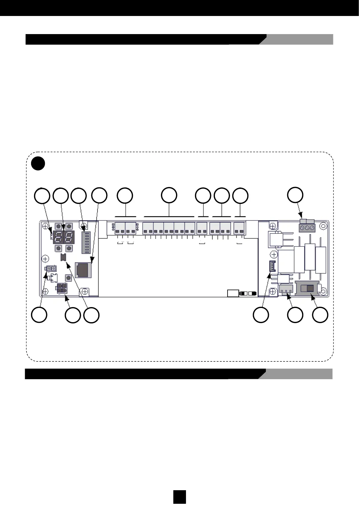
5.10 VECTOR Electronic Card
Fig. 22 shows the main components of the electronic card:
I - Controls/inputs connectors
J - Power supply for the sensors/accessories
K - Multi-logical program switch connector
L - Electronic lock connector
M - Key-pad connector
N - Motor connector
O - Braking level selector connector
P - Arm type program switch
A - Jumper to display viewing
B - Display and buttons
C - Dip switches
D - PC connector
E - Transformer connector
F - ON-OFF switch connector
G - Logic setting selection switch connector
H - Auxiliary output connections
Fig. 22
5.11 Electronic Connections
• Logic settings switch connector [H]
• ON-OFF switch connector [G]
• Transformer connector [E]
• Motor connector [O]
• Key-pad connector [N]
Connect to the electronic card (Fig. 22):
A
O D
G F
E
C
H
I J K
B L
M
N P
LOCK
GND
DATA
PWF
RST
OUT
15VDC
COM
AUX- IN2
AUX- IN1
START 2
START 1
COM
KEY
SAFE - CLOSE
SAFE - OPEN
COM
AUX– OUT2
AUX– OUT1
A
B
A
B
+
-
-
+
RIGID ARM
ARTICULATED ARM
MANUAL
I O II
TWO RADARS
STOP OPEN