K
Karen LeAug 2, 2025
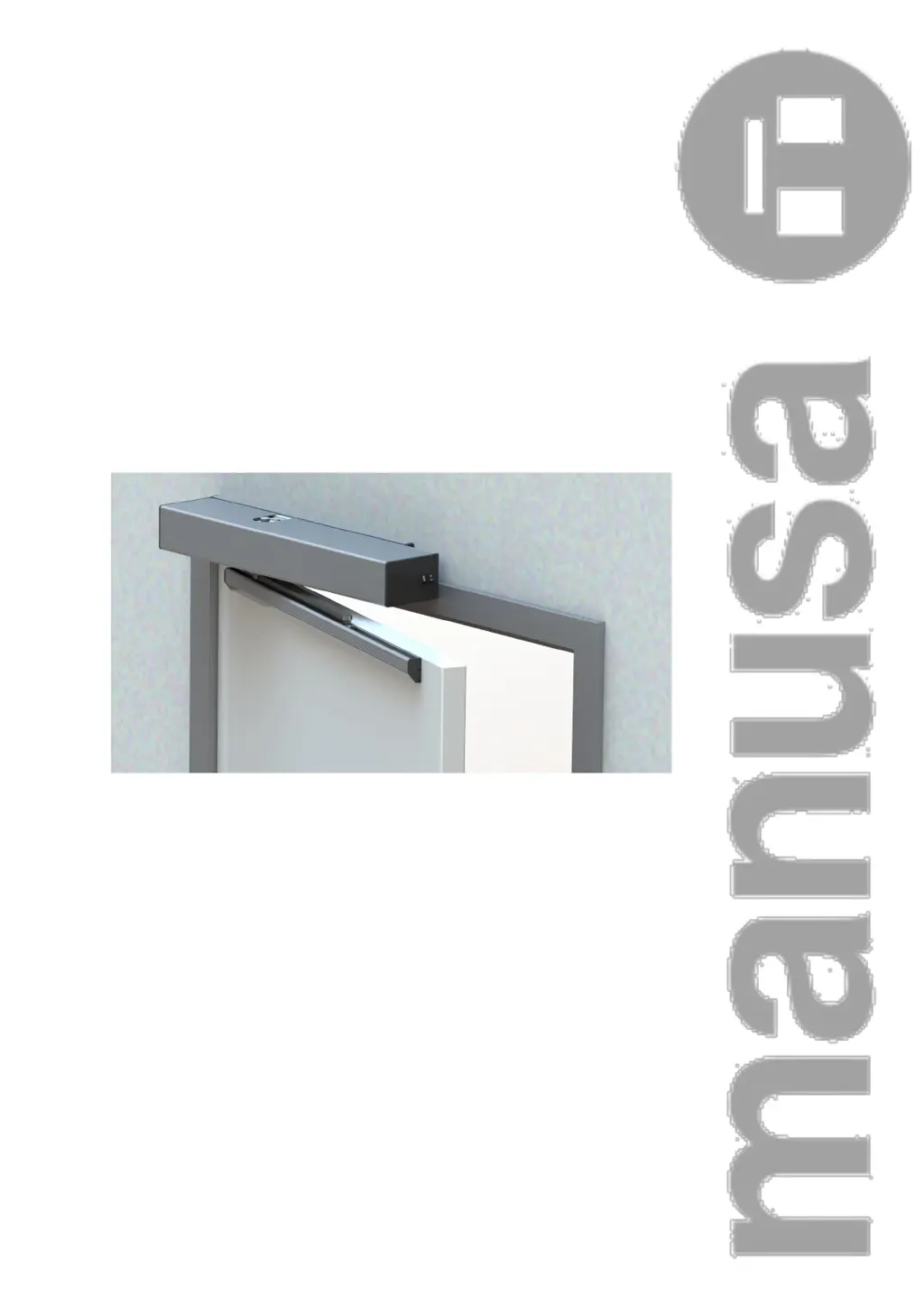
What to do if there is an anomaly in Manusa VECTOR Door Opening System operation?
- JjeanetteparksAug 2, 2025
If you notice an anomaly in the Manusa Door Opening System, first select the door open mode and then switch to the automatic door mode. If the problem continues after this, it's recommended to contact an authorized Manusa service technician for assistance.