ENGLISH
Part
names
and
functions
For buttons not explained
here, see the page indicated
in
pa
re
ntheses (
).
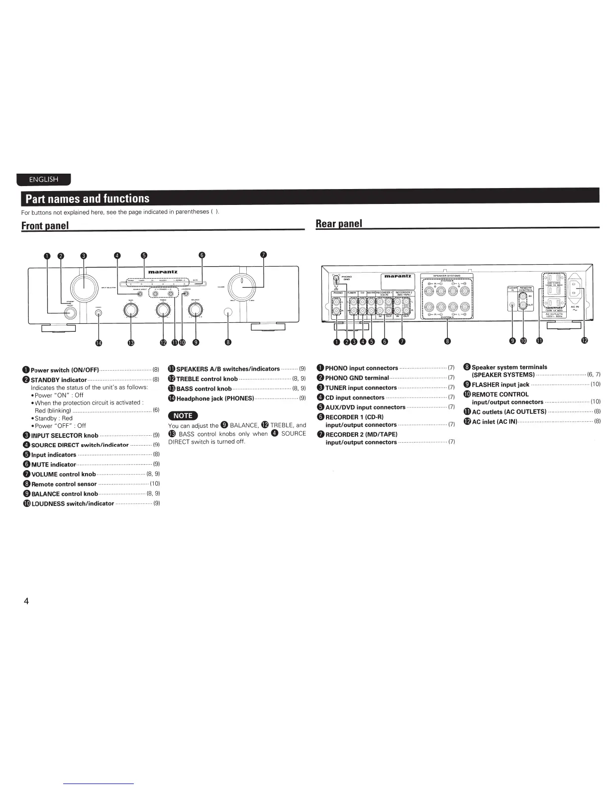
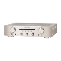
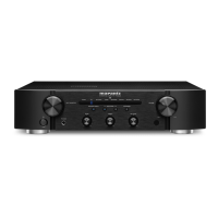
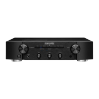
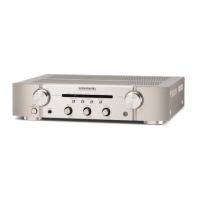
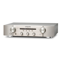
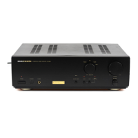
Front
panel
0
Power
switch
(ON/OFF)
f.J
STANDBY
indicator
···
··
······(8)
......... .......
····(8)
Indicates the status of the unit's
as
follows:
•
Po
wer
"ON"
:Off
•
When the protection circuit is activated :
Red
(blinking)
..
..
...
....
...... . ........................ ..
(6)
•
Standby :
Red
• Power "
OFF
"
:Off
OINPUT
SELECTOR
knob
· · · · ·
(9)
Q
SOURCE DIRECT
switch/indicator
· · ·
(9)
01nput
indicators
· · · · · · · · · · · · · · ·
··
· · · · · · · · · · · · · · ·
(8)
0 MUTE
indicator
·
··
······
···
· · · · · · · · · · · · · ·
··
· · · · · · ·
··
· · · · · ·
(9)
8 VOLUME
control
knob·
· · · ·· · ·
(8,
9)
fit
Remote
control
sensor
··
·
·· ··
·
··
·
··
(1
0)
0
BALANCE
control
knob
··
··
(8,
9)
41)
LOUDNESS
switch/indicator
· · · · · · · · · ·
(9)
4
4D
SPEAKERS
A/B
switches/indicators
·
··
· · · · · ·
(9)
f/TREBLE
control
knob
···
···
·
··
···
···
······
(8,
9)
41
BASS
control
knob··· · · · · · · · · · · · · ·
(8,
9)
41Headphone
jack
(PHONES)·····
··
··········
(9)
4¢l•U*
You
can
adjust the
0
BALANCE,
fl
TREBLE
, and
41
BASS
cont
rol
knobs
only
when
Q SOURCE
DIRECT
swi
tch is turned
off
.
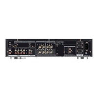
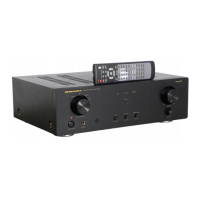
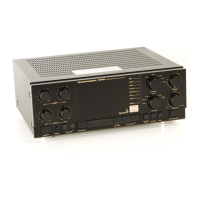
Rear
panel
~
..............
SYSTEU
'"'B••••••·····
!
~
l
ii
~
i
!
~
~~~~
~
:
$-A-B
&-
L
--<:;9
:
•
SVSTF.U
A :
0 PHONO
input
connectors
· · · · · · · · ·· · · · · · ·
f.J
PHONO
GND
terminal·
·····
(7)
.. ... (7)
·····
(7)
..... (7)
fit
Speaker
system
terminals
(SPEAKER
SYSTEMS) · ·
....... (6, 7)
·(10)
C)
TUNER
input
connectors
Q
CD
input
connectors
· · ·
0
AUX/DVD
input
connectors
0RECORDER
1 (CD-R)
input/output
connectors ·
8RECORDER
2 (MD/TAPE)
. (7)
..... (7)
input/output
connectors·· ·······
··
···········
··
··
·
(7)
0
FLASHER
input
jack
·
··
41)
REMOTE
CONTROL
input/output
connectors ····· ······
··
········
····
(1
0)
4D
AC
outlets
(AC
OUTLETS) · ·
(8)
f/AC
inlet
(AC IN)·········
·· ··
········
···
(8)