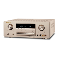
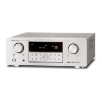
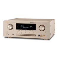
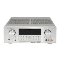
AV Surround Receiver
TABLE OF CONTENTS
SECTION PAGE
1. LOCATION OF PRINTED CIRCUIT BOARDS/VERSION VARIATIONS ................................................ 1-1
2. TECHNICAL SPECIFICATION ................................................................................................................ 1-3
3. SERVICE TOOL/MEASUREMENT SET UP/SAFETY ............................................................................ 1-5
4. WARNING/HANDLING CHIP COMPONENTS ....................................................................................... 1-6
5. DISMANTLING HINTS ............................................................................................................................ 2-1
6. ABREVIATIONS ...................................................................................................................................... 2-2
7. WIRING DIAGRAM.................................................................................................................................. 3-1
8. BLOCK DIAGRAM ................................................................................................................................... 4-1
9. SERVICE TEST PROGRAM ................................................................................................................... 5-1
10. FRONT BOARD....................................................................................................................................... 6-1
11. TUNER BOARD ECO5 ..........................................................................................................................7B-1
12. TUNER 95 BOARD............................................................................................................................... 7D-1
13. DOLBY PROLOGIC BOARD ................................................................................................................... 8-1
14. MULTI-CHANNEL DECODING MODULE ............................................................................................... 9-1
15. MAINS BOARD...................................................................................................................................... 10-1
16. MONO BOARD ...................................................................................................................................... 11-1
17. EXPLODED VIEW ................................................................................................................................. 12-1
18. ELECTRICAL PARTS LIST MONO BOARD ......................................................................................... 13-1
Service
Manual
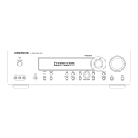
SR3000 /N1B, /U1B
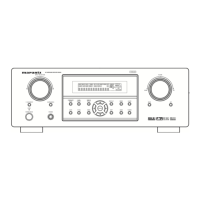
SR4000 /K1B, /K1G, /N1B, /U1B
Please use this service manual with referring to the user guide (D.F.U) without fail.
R
SR3000 / SR4000
283W855010 ACT
3120 785 22200
First Issue:2000.03
SR3000
SR4000