MR 150M–1050M SINGLE – MXIII CONTROLLER
OPERATION
27
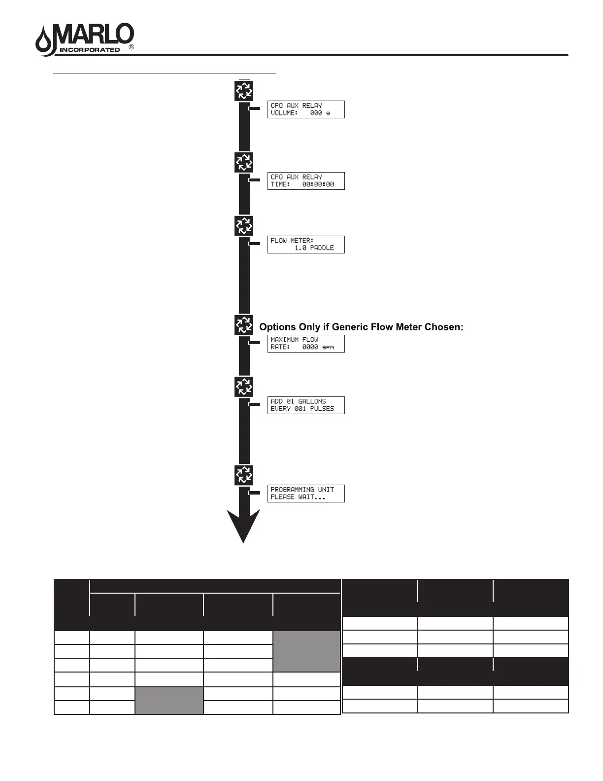
MASTER PROGRAMMING MODE FLOW CHART
Example:
Chemical Pump Auxiliary Relay
Volume at 0 Gallons
Range: 000 to 999 gallons in U.S. Format
0.000 to 9.999 m3 in Metric Format
Example:
Chemical Pump Auxiliary Relay at 0 Hours,
0 Minutes, & 0 Seconds
Range: 00:00:00 to 02:00:00
Example:
1.0 Paddle Flow Meter
Options: 1.0 Paddle
1.0 Turbine
1.5 Paddle
1.5 Turbine
2.0 Paddle
3.0 Paddle
Generic
Example:
Maximum Flow Rate of 0 gpm
Range: 20 - 2,000 gpm (U.S. Format)
2.0 - 200.0 m3 (Metric Format)
Range: 1 - 99 Gallons (U.S. Format)
0.1 - 09.9 M3 (Metric Format)
Pulses: 1 - 99
Example:
Master Programming Mode is Exiting
Options: Gallons (U.S. Format)
Meter3 (Metric Format)
Example:
Add 1 Gallon for Each Pulse in U.S. Format
NOTE: Only displayed on units that
physically have a meter (Lead
always has a meter). Only shown if
Auxiliary Relay is disabled on
System Types 6 & 7.
NOTES: Default flow meter type is
based on the valve type. This screen
will only display on the lead unit for
System Types 6 & 7. All other system
types it will display for all units.
OPTIONS FOR GENERIC FLOW METER SETTING
K-FACTOR TABLE
CLACK METER MAX FLOW RATE K-FACTOR
(in) (gpm) (Pulses per Gallon)
1-1/2 75 37
2 150 20
3 350 8
AUTOTROL METER MAX FLOW RATE K-FACTOR
(in) (gpm) (Pulses per Gallon)
1 25 65
2 255 15
PIPE
SIZE
SIGNET 2536 FLOW SENSOR SETTINGS
MAX FLOW
RATE
TEE
GALVANIZED
TEE
PVC
SADDLE
IRON
(in) (gpm) (Pulses per Gallon)
1 49 213 352
1-1/4 76 128 177
1-1/2 110 94 118
2 195 59 67 54
2-1/2 306 43 38
3 440 27 23