3-6 MASTERFLEX
®
Digital Pump Drive Operating Manual Masterflex
Section 3
Operation
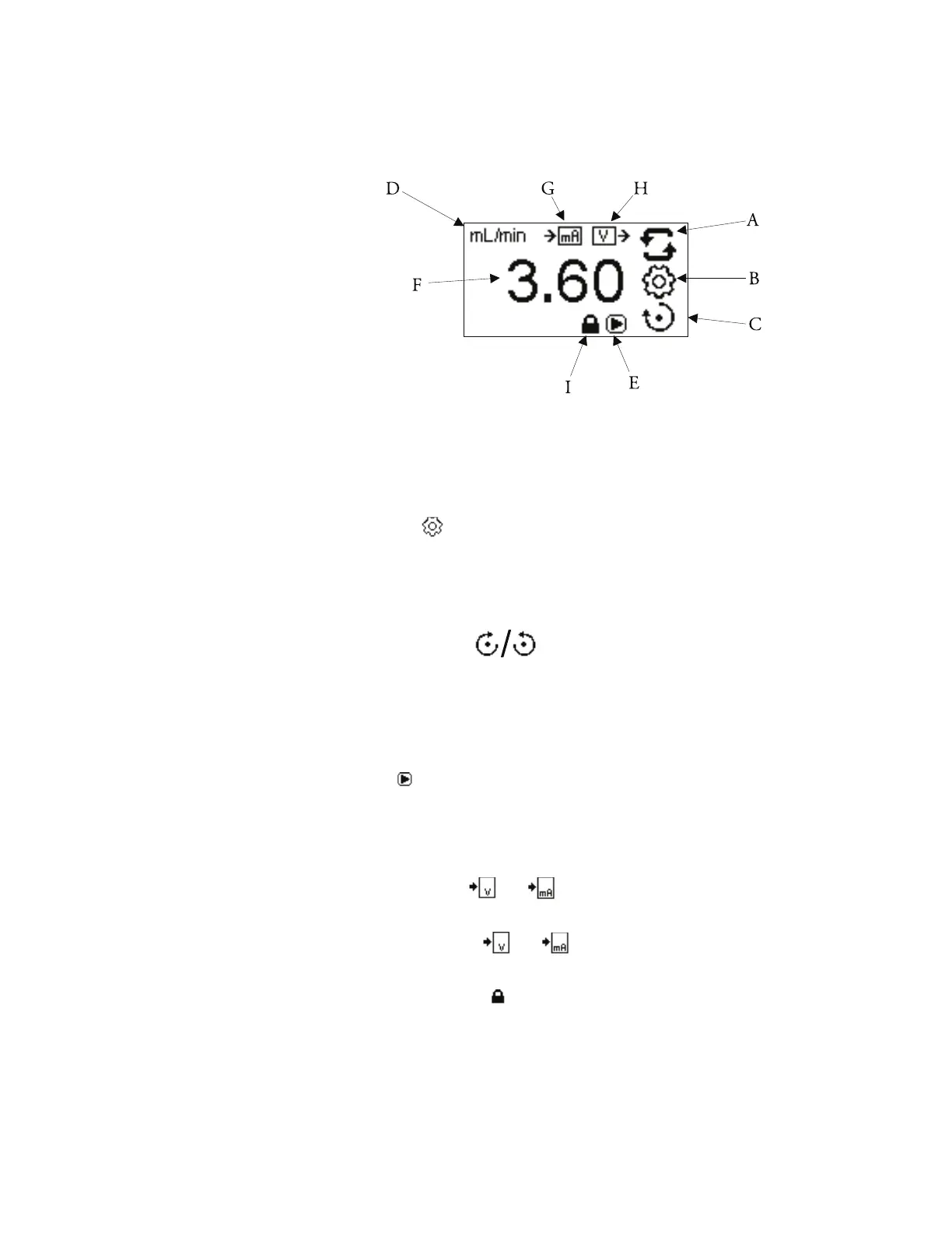
Display Legend: Below is a screenshot of the screen display for the drive in
Continuous Mode. An explanation of the information on the screen follows.
Figure 3-3. Continuous Mode Screen.
A. Mode Display: Current operating mode in which the drive will operate.
Pressing ENTER key when highlighted will cycle through the different
operation modes.
B. Settings : Pressing the ENTER key on this icon goes to the Settings
Menu. e Settings Menu contains all the functions for Continuous
Mode, which includes: Flow Units, Tubing Size, Remote Control, and
Keypad Lockout. e Settings Menu also provides access to tubing
calibration and sounds.
C. Flow Direction : Pressing the ENTER key on this icon toggles
between clockwise and counterclockwise flow direction. This icon will
rotate when the pump is running.
D. Flow Units: Informative only. NOTE: Flow units are available in
Continuous Mode only.
E. Play : Informative only. is icon will display when the pump is
running.
F. Flow Rate: e center digits show the flow rate of the drive in the unit of
measure selected.
G. Remote Input or : Informative only. Voltage input or Current
input will display when turned on in the settings menu.
H. Remote Output or : Informative only. Voltage output or
Current output will display when turned on in the settings menu.
I. Keypad Lockout : Informative only. is icon will display when the
keypad lockout is turned on in the setting menu. Locking the keypad will
prevent someone from changing the settings on the drive.
Continuous Mode
Screen (continued)