10
|
EN / SunMaster CS15TL RP / CS20TL RP / CS30TL RP
4 BEFORE YOU START
4.1 TRANSPORT, LIFTING AND STORAGE
Ensure adequate and secure packaging during
transportation of the CS inverter. Always use
suitable handling equipment for transportation.
More than two persons may be required to
hang the CS inverter to a wall, refer to local
safety standards.
The CS inverter is shipped in a wooden crate that can be
handled with a fork lift. In order to prevent damage, always
transport the CS inverter in its transportation crate. Minimum
two persons are required to unpack the CS inverter and to lift
it out of its box.
4.2 INSTALLATION ENVIRONMENT
The CS inverter is designed for both indoor and outdoor use,
protection degree is IP65.
Operating conditions:
• -20 to 60°C, relative humidity 4% to 100% condensing.
• Power derating at temperatures above 45 °C.
• Start-up at temperatures above -10 °C
CAUTION!
Do not install in aggressive environments like
ammonium, acids and salt air.
CAUTION!
Do not install in areas that are subject to the
risk of gas- or dust explosions.
4.2.1 For all installations
• If the CS inverter is installed in the immediate vicinity of
living areas, take into account that it can produce a certain
noise level when operating.
• Hang the CS vertically to a sufciently strong, solid wall,
no other angle other than straight up is allowed.
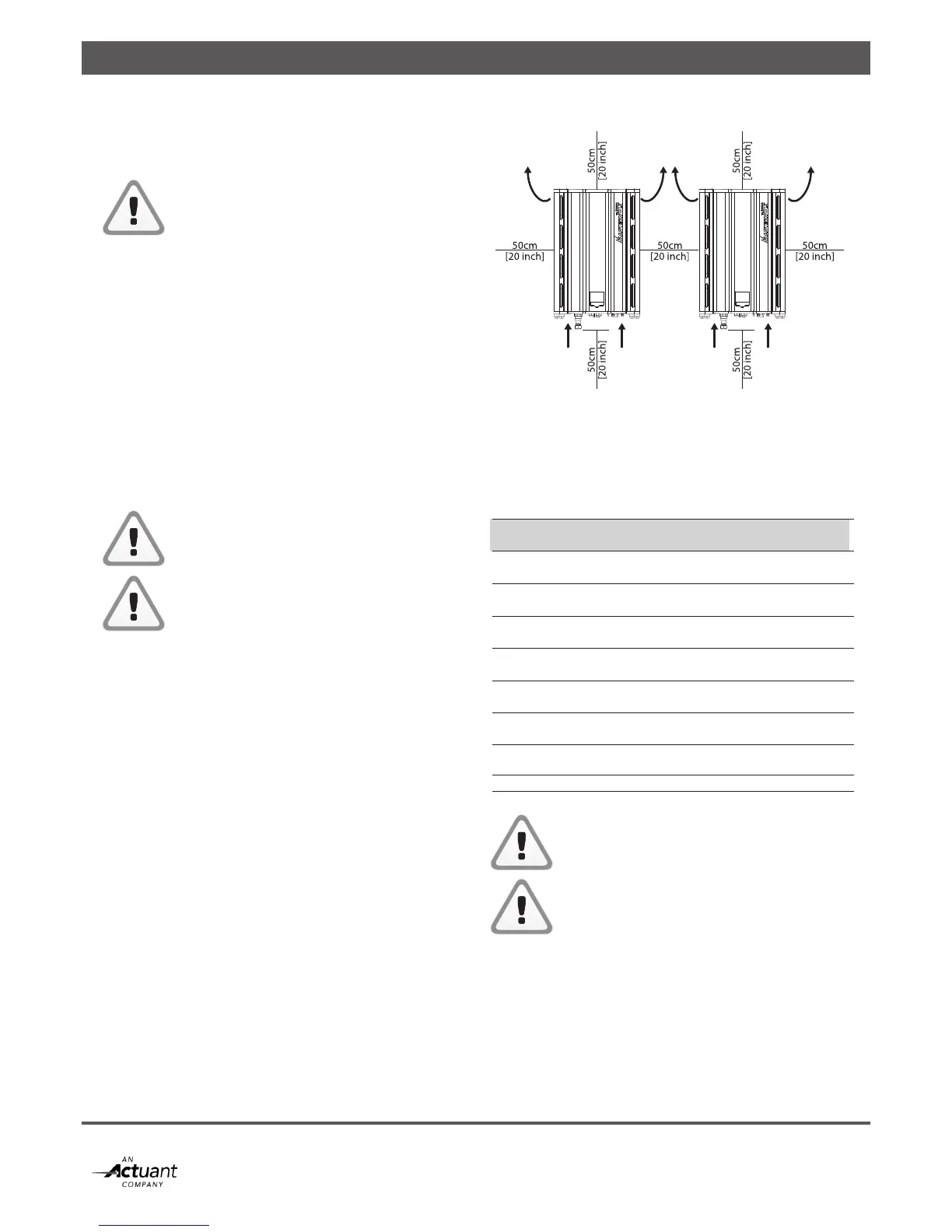
• Keeping at least 50 cm space around the CS inverter is
recommended, see fig. 4-1.
4.2.2 For indoor installations
• Maintain sufcient ventilation and enough distance around
each inverter to prevent build up of hot air.
4.2.3 For outdoor installations
• Prevent placement in direct sunlight as this warms up the
inverter, resulting in performance loss.
• Shield the inverter against direct rain when possible to
avoid corrosion.
• In humid atmospheres with large temperature differences,
moisture may gather behind the display screen. If this
persists, contact your Mastervolt supplier.
Figure 4-1: Mounting distance
4.3 DC INPUT SPECIFICATIONS
The PV installation to which the inverter is connected should
meet the following input specifications.
DC Input specifications per input
Model CS15TL RP CS20TL RP CS30TLRP
Absolute max. 1000VDC 1000VDC 1000VDC
Input Voltage
Operating 200VDC – 980VDC
voltage
Full power 350VDC – 350VDC – 460VDC –
voltage 800VDC 800VDC 800VDC
Max. input 23ADC 30ADC 34ADC
current
Maximum 9,5 kWp 12,5 kWp 19,0 kWp
PV power
Recommended 9,0 kWp 11,5 kWp 17,5 kWp
PV power
Maximum array 6 µF total for 2 inputs
capacitance
Max. PV I
SC
30A 30A 34A
Never connect voltages higher than 1000V DC
to the inverter, as this will cause permanent
damage to the inverter.
The inverter will automatically limit the input
current and power to its specified rating. Excess
power will not be converted.
Air inlet Air inletAir inlet
Air outlet Air outletAir outlet