|
31
EN / SunMaster CS15TL RP / CS20TL RP / CS30TL RP
10.3 ACTIVE POWER MANAGEMENT
This section describes all types of power management
available on the SunMaster CS inverter.
10.3.1 Power management by Telecontrol
For some PV installations, the local grid operator (Distribution
Network Operator, DNO) may require the possibility to reduce
the power output of the PV plant by remote commands. In
such case, a Telecontrol receiver must be installed.
The SunMaster CS can respond to the power commands
when a Data Control Premium II or Data Control Pro is
connected to the inverter by RS485. A single datalogger
can control up to 20 inverters at the same time. Contact your
Mastervolt supplier for more information.
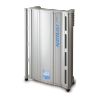
In case the DNO sends a Power Management request to
the plant, the CS inverter dislay will show the current
reduction value in the display in the Home Screen.
Refer to figure 10-5.
Figure 10-5: Home screen, the Warning can be a power reduction
10.3.2 Frequency dependent power control
The SunMaster CS can reduce its output power
autonomously if the grid frequency exceeds the nominal
value. The inverter has two available control laws.
1. Control Law 1 (compliant to VDE-AR-4105)
2. Control Law 2 (compliant to BDEW)
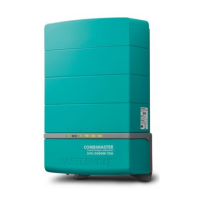
Figure 10-6: Control Law 1 (compliant to VDE-AR-4105)
The inverter will start reducing the output power when the
grid frequency exceeds the fstart value. The power reduction
(Gradient) is defined as a percentage of actual output power
per hertz, according to the following formula:
∆P = Gradient*fstart - factual
Pm is the inverter output power when fstart was exceeded
Gradient is the relative power reduction per hertz
fstart is the control trip frequency
factual is the actual measured grid frequency
• When the grid frequency rises above fstart, the inverter
memorizes the actual output power generated at that
moment. The memorized power is stored as Pm.
• For any grid frequency above fstart, the output power is
reduced with the defined Gradient.
• When the grid frequency drops below fstart, the inverter
will return to full power operation
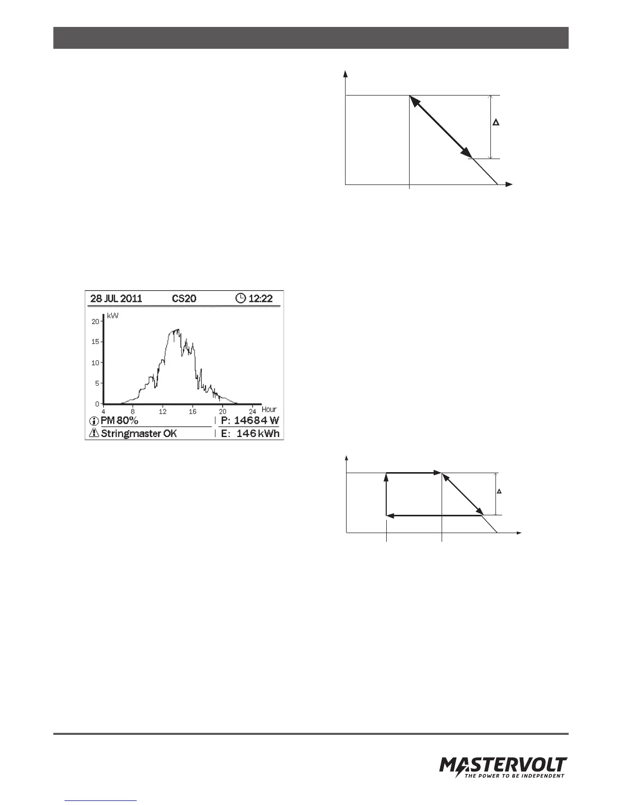
Figure 10-7: Control Law 2 (compliant to BDEW)
Refer to figure 10-7. The inverter will start reducing the
output power when the grid frequency exceeds the fstart
value. When the grid frequency is reduced, the inverter will
clamp the output power to the lowest value achieved, until
the frequency has dropped below the predefined recovery
frequency frecover.
Available Parameters
A single set of parameters are available to fine-tune the
inverter behavior for both control laws. If the VDE compliant
control law is selected, frecover parameter is ignored. The
Ramp-Up parameter specifies the speed at which the inverter
0
P
m
f [Hz]
P
f
start
P
G r a d i e n t : % / H z
f
recover
0
P
m
f [Hz]
P
f
start
P
G r a d i e n t : % / H z